Carl Zeiss
Axiotech and Axiotech
vario
3-40
B 40-020 e 06/99
•
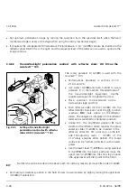
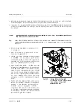
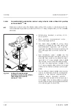
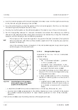
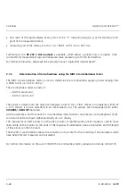
Insert micrometer eyepiece with clamped integrated micrometer screw into the right tube and clamp
it onto the tube using the clamping screw (3-35/
9
).
•
Focus the reticle figure by turning the eyelens on the micrometer eyepiece, then focus on the object.
The reticle figure and the object must be in focus.
•
Focus by turning the eyelens on the additional eyepiece. The object is now in focus in the binocular.
•
Set the interpupillary distance for binocular observation and adjust the measuring axis (shifting
direction of the measuring marks) of the object structure to be measured by turning the micrometer
eyepiece, with the clamping screw (3-35/
9
) being loosened.
☞
The clamping of the micrometer eyepiece in any position between horizontal to the right and
vertical downwards (with little overflow) enables adjustment of the measuring axis positions
required for measuring.
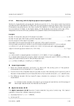
Use of this accessory ensures conjugation of the intermediate eyepiece image (reticle figures)
and the images on the camera/TV port.
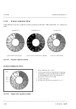
3.7.2.2
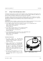
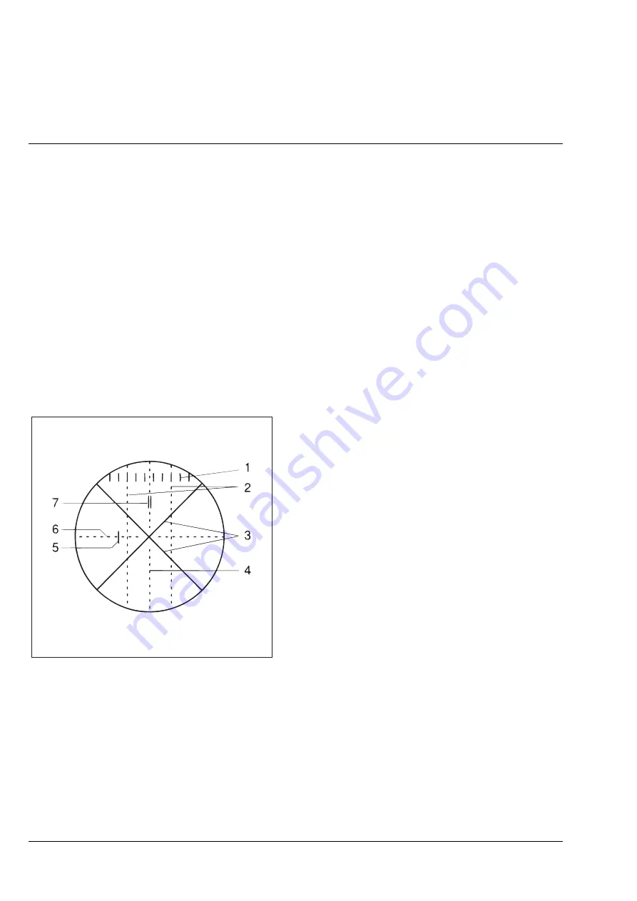
Using crossline figures
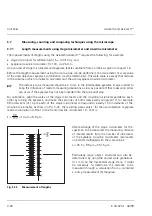
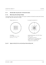
Appearance
of the dia. 18 mm intermediate
eyepiece image:
•
fixed positions:
−
the unnumbered
millimeter gradation
l = 10 mm (3-36/
1
), and
−
two dashed lines perpendicular to the
millimeter gradation, each 3 mm to the left
and right of the field center (3-36/
2
);
•
the following markings can be shifted within a
range of
±
5 mm from the image center using
the integrated micrometer:
•
a reticle (3-36/
3
) slanted at 45° to the shifting
direction for scanning points on contours with a
bent line,
−
a dashed line ( 3-36/
4
) perpendicular to the
shifting direction (to touch convex contours
or to enable congruence with straight-line
edges),
−
a double line (3-36/
7
) to trap narrow straight lines or to touch tips, fiber ends, etc., and
−
one short line (3-36/
5
) perpendicular to the shifting direction and 4 mm to the left of the dashed
line ( 3-36/
4
) to enable measurement of object details positioned in front of the millimeter
gradation.
The flush line (3-36/
6
) marks the shifting direction of the adjustment marks.
Fig. 3-36
Crossline figure in the eyepiece
intermediate image of the digital
eyepiece measuring device
Summary of Contents for Axiotech
Page 1: ...Axiotech and Axiotechvario Materials Microscopes Operating Manual...
Page 14: ...Carl Zeiss Axiotech and Axiotechvario XIV B 40 020 e 06 99...
Page 16: ...Carl Zeiss Axiotech and Axiotechvario 1 2 B 40 020 e 06 99...
Page 112: ...Carl Zeiss Axiotech and Axiotechvario 3 46 B 40 020 e 06 99...
Page 114: ...Carl Zeiss Axiotech and Axiotechvario 4 2 B 40 020 e 06 99...
Page 124: ...Carl Zeiss Axiotech and Axiotechvario A 2 B 40 020 e 06 99...

