3D Microscopy
Axiovert 100/135/135 M
Contents
B 40-022-4 e 09/98
15
3D Microscopy for
Axiovert 100/135/135 M
Contents
1
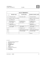
Components for 3D Microscopy
Overview .................................................. 16
2 Eyepiece
version................................................................................................ 18
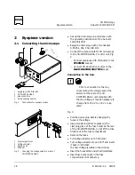
2.1
Converting the microscope .............................................................................................. 18
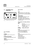
2.2
3D-CONTROL DSA-3 Control Unit .................................................................................... 20
2.2.1 Connections..................................................................................................................... 20
2.2.2 Controls........................................................................................................................... 20
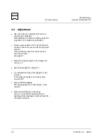
2.3 Adjustment ...................................................................................................................... 21
2.3.1
Adjustment of 3D illumination shutter.............................................................................. 21
2.3.2
Check the contrast........................................................................................................... 22
2.3.3
Check whether image is upright ...................................................................................... 23
3 Monitor
version................................................................................................. 24
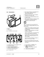
3.1 Conversion....................................................................................................................... 25
3.2
MCU II Control Unit ......................................................................................................... 27
3.2.1 Controls........................................................................................................................... 27
3.2.2
Basic settings for 3D microscopy ...................................................................................... 27
3.3 Adjustment ...................................................................................................................... 28
3.4
3D video recordings ......................................................................................................... 29
3.5
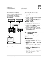
Printing of 3D video recordings ........................................................................................ 29
4
Eyepiece and monitor version ......................................................................... 30
4.1
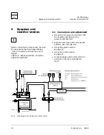
Conversion and adjustment ............................................................................................. 30
4.2 Observation ..................................................................................................................... 31
4.2.1 Eyepiece
observation........................................................................................................ 31
4.2.2 Monitor
observation ........................................................................................................ 31
Illustrations
Fig. 1
Overview ......................................................................................................................... 16
Fig. 2
Connections for eyepiece version ..................................................................................... 18
Fig. 3
Changing the voltage selector on rear of 3D-CONTROL DSA-3 ........................................ 18
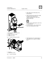
Fig. 4
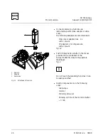
Insertion of 3D illumination shutter .................................................................................. 19
Fig. 5
Insertion of depolarizer .................................................................................................... 19
Fig. 6
3D-CONTROL DSA-3 control unit, front ........................................................................... 20
Fig. 7
Adjustment of 3D illumination shutter, pupil .................................................................... 21
Fig. 8
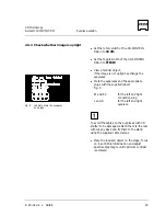
Labels to mark the eyepieces and plugs............................................................................ 23
Fig. 9
Wiring diagram for monitor version ................................................................................. 24
Fig. 10 Attachment of monitor shutter ........................................................................................ 25
Fig. 11 Rear of MCU II ................................................................................................................. 25
Fig. 12 Attachment of camera ..................................................................................................... 26
Fig. 13 MCU II controls, front ...................................................................................................... 27
Fig. 14 Wiring diagram for video prints........................................................................................ 29
Fig. 15 Wiring diagram for eyepiece and monitor versions ........................................................... 30


