HDS4x2 User Guide, Rev 1.1, 08-31-07
20
IR Jack, IR Format and IR Codes
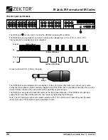
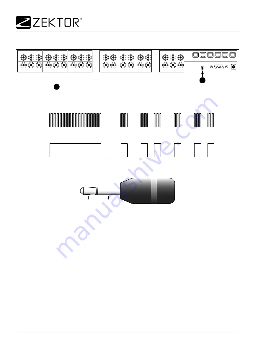
IR control jack specifications
IN-1
IN-3
IN-2
IN-4
OUT
-1
ANALOG
AUDIO INPUT
ANALOG
AUDIO OUTPUT
DIGIT
AL
AUDIO
OUT
-2
RS232
9VDC
IR-IN
Y/G Pb/B Pr/R
Y/G Pb/B Pr/R
Y/G Pb/B Pr/R
Y/G Pb/B Pr/R
Y/G Pb/B Pr/R
Y/G Pb/B Pr/R
IN-1
R IN-1 L
R IN-2 L
R IN-3 L
R IN-4 L
R OUT-1 L
IN-1
IN-2
OUT-1
IN-3
IN-4
OUT-2
R OUT-2 L
IN-2
IN-3
IN-4
OUT-1 OUT-2
The IR-IN jack
1
can be used to control the HDS4x2 using any IR controller.
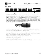
The IR-IN jack is non-polarized, and can be driven with voltages from +3V to +15V, or -3V to -15V.
The signal can be modulated or un-modulated:
30KHz to 500KHz
3V to 15V
0V
MODULATED SIGNAL
UNMODULATED SIGNAL
3V to 15V
0V
It uses a standard 1/8” (3.5mm) mini-plug:
SLEEVE
TIP
The IR-IN jack is opto-isolated and non-polarized. It does not matter which way you connect your source
across the tip and sleeve of the connector. Neither side of the IR-IN jack is grounded, and either the tip or the
sleeve can be connected to ground without the possibility of ground loops.
The IR-IN jack recognizes the same IR codes as the front panel IR sensor. If the HDS4x2 is taught new
codes, these new codes will become the new codes recognized by the IR-IN jack.
Note: The IR control jack option is mutually exclusive with “12V on/off control” option (they use the same
jack!). Only one of these options can be enabled at a time.
11


