background image

Once


entered


there


will


be


3


beeps


and

!

!


system


will


return


to


normal

!

The


front


panel


indicators


will


be


as


follows:

!

!!

!

  Mode


Indicator


=    

!

!


Door


Indicator


=

!

Changing


the


access


codes

!

!

Step 1 – Enter Programming mode

!


Press


#


key


twice


quickly


within


5


seconds

!

Enter


1234


quickly

!

The


controller


has


now


entered


programming

!

mode


and


the


front


panel


door


indicator

!

should


have


changed


from


RED


to


GREEN.

!

!

Step 2 – Changing the front door code

!

Press


1


(The


front


panel


indicators


must


still

!

!


show


as


indicated


in


step


1)

!

Enter


new


code

!

Once


entered


there


will


be


3


beeps


and

!

!


system


will


return


to


normal

!

The


front


panel


indicators


will


be


as


follows:

!

!!

!

   Mode


Indicator


=

!

!


Door Indicator =

!

!

Step 3 – Changing the back door code

!

Start


process


again


at


STEP


1


to


enter

!

!


programming


mode


once


again

!

Press


2


(The


front


panel


indicators


must


still

!

!


show


as


indicated


in


step


1)

!

Enter


new


code

!

Once


entered


there


will


be


3


beeps


and

!

!


system


will


return


to


normal

!

The


front


panel


indicators


will


be


as


follows:

!

!!

!

Mode


Indicator


=

!

!

Door


Indicator


=

!

9

!

Zellabox

!

Technical


data

!

!
!


4


Technical


data

!


4.1


Access


control

!

4.1.1 Metal Keypad


Key


Features

!

!

500


Users

!

Water


and


vandal


resistant

!

Backlight


(Backlit


family,


option


“B”)

!

Three


user


levels:


normal;


secure;


master

!

Three


modes


of


operation:


normal;


bypass;

!

!


secure

!

Integrated


keypad


for


PIN


entry


(Piezo

!

!


electric


-


Q44


only)

!

Integrated


proximity


card


reader


(Q42


and

!

!


Q44


only)

!

Selectable


PIN


code


length


up


to


8


digits

!

Auxiliary


input


and


auxiliary


output

!

Ten


auxiliary


modes


including:


door


ajar;

!

!


forced


door;


shunt;


door


monitor;


normal/

!

      secure;


LED


control

!

Input


for


Request


to


Exit


(REX)


button

!

     Code


search


feature


for


easy


maintenance

!

     of


user


codes

!

Internal


buzzer

!

Vandal


proof


screw


(special


tool


supplied)

!

Two


tri-colour


LED


indicators


for


status


/

!

     programming


Interface

!

Built-in


case


and


back


tamper


protection

!

Lockout


feature


on


wrong


entries

!

     (Keypad/Card


Tamper)

!

Bell,


chime,


siren


and


strobe


features

!

     available


with


BL-D40

!

Programmable


siren


time


(with


BL-D40)

!


Programmable


lock


strike


release


time.

!

!


Supplied


with


mounting


template


for


easy

!

!


installation

!

!


!

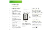
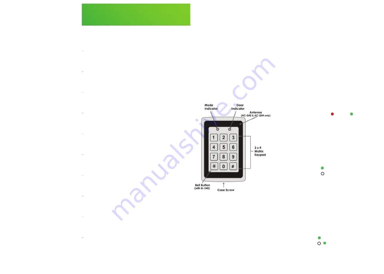
          Front


panel


description

!

Summary of Contents for Cubb

Page 1: ...1 Zellabox User Manual...

Page 2: ...2 Pyrorack 2 3 Uninterruptible Power Supply 2 4 Switchboard 3 Start up procedure 4 Technical Data 4 1 Access Control 4 2 Pyrorack 4 3 Uninterruptible Power Supply 4 4 Switchboard 4 5 Cooling System 4...

Page 3: ...nd robust environment The Micro Data Centre eliminates the need for a server room Our micro data centres offer a robust and dependable answer to the question of housing and securing your networking an...

Page 4: ...ructions 2 1 Overview Important safety note Caution needs to be taken when removing the side panels of the Micro Data Centre in particular when dealing with the 38U as they are heavy we recommend a 2...

Page 5: ...ted Avoid exposure to the fire by products and extinguishing mixture Should it be necessary to enter the area before it is fully ventilated the use of a respirator or other means of protection may be...

Page 6: ...p on or trip over them Do not connect domestic appliances such as hair dryers to UPS output sockets The UPS can be operated by any individuals with no previous experience Connect the UPS system only t...

Page 7: ...e take the precautionary measures specified below and any other measures necessary when working with batteries Remove wristwatches rings and other metal objects Use only tools with insulated grips and...

Page 8: ...DO NOT exceed the cooling system s recommended BTU h specifications listed in the cooling system section as this will overheat the equipment The Zellabox Micro Data Centre is a PLUG N PLAY unit theref...

Page 9: ...nt panel indicators will be as follows Mode Indicator Door Indicator 9 Zellabox Technical data 4 Technical data 4 1 Access control 4 1 1 Metal Keypad Key Features 500 Users Water and vandal resistant...

Page 10: ...Water and vandal resistant Backlight Backlit family option B Three user levels normal secure master Three modes of operation normal bypass secure Integrated keypad for PIN entry Piezo electric Q44 on...

Page 11: ...irements The installation of this product should only be carried out by a competent person and comply with applicable current National or International standards 11 Zellabox Technical data 4 2 Pyrorac...

Page 12: ...base correctly also check that the end of line resistor is in place on the detector base 4 2 3 3 System Fault Cause see all other Fault Indications and Detectors Remedy Check Detectors in place and p...

Page 13: ...t every 3 months the following checks are carried out by a competent person Entries in the Log Book are checked and any necessary action taken Batteries and their connections should be examined and te...

Page 14: ...Zellabox Technical data 4 3 Uninterruptibale power supply 4 3 1 Introduction Please refer to relevant UPS User Manual provided in the Zellabox or alternatively go online 14...

Page 15: ...res Functions The switchboard is plugged or hardwired directly into the building s power source and has a green light on the front panel which MUST be illuminated at all times indicating there is a po...

Page 16: ...but rather switching the cooling system off at the switchboard to reset the controls The recommended temperature setting is between 20 and 23 degrees for maximum efficiency Problem Potential Cause So...

Page 17: ...ratures over 42 degrees within the data centre while a cooling unit is running the alternate unit will start up and provide extra cooling for the Micro Data Centre Once the temperature drops below 20...

Page 18: ...ffer a simple user experience for seamless physical deployment configuration commissioning monitoring and power delivery Zellabox power distribution hardware will remain in place through multiple tech...

Page 19: ...19 Zellabox Zellabox Pty Ltd PO Box 1035 Osborne Park DC Western Australia 6916 AUSTRALIA 1300 117 644 www zellabox com info zellabox com Version 2016 007...

Reviews: