
27
GW24-011_v02
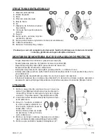
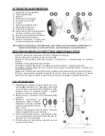
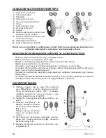
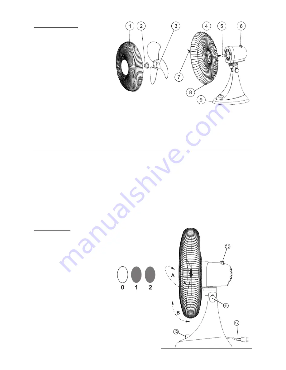
FAN OUTLINE
1.
Front protecting grill.
2.
Plastic nut.
3.
Propeller.
4.
Back protecting grill.
5.
Retaining pin.
6.
Stand.
7.
Circlip of grills.
8.
Protecting grill fastener.
9.
Base.
10.
Head oscillation button.
11.
Fan leaning adjustment knob.
12.
Supplying cord.
13.
ON/OFF and rotation buttons.
The product you purchased is partially disassembled.
Assemble thoroughly before usage according to the following description.
PROPELLER AND PROTECTING GRILLS ASSEMBLING/DISSEMBLANCE
Move the grill fasteners
–
(7)
outside.
Remove front protecting grill from the circlip
–
(8)
.
Unscrew plastic nut
–
(2)
clockwise.
Remove the propeller
–
(3)
from the fan shaft.
Set the back protecting grill
–
(4)
in right position – handle upright.
Assemble the propeller
–
(3)
at the shaft, so that retaining pin
(5)
got into the recess at the fan
hub.
Turn plastic nut
–
(2)
to the fan shaft counter-clockwise.
Insert the bottom edge of front grill
–
(1)
into the circlip
(8)
, press it towards back grill
(4)
and press
protecting grill fasteners
(8)
inside.
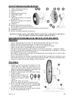
HANDLING
1.
Select the airflow direction upwards or a bit down
-
wards
(B)
untighten the leaning adjustment knob
(11)
and set the best angle of head leaning – air
-
flow. Tighten the knob
(11)
.
2.
Insert supplying cord
(12)
into mains supply outlet.
3.
Switch on selected rota
-
tion speed pressing rotation
button
(13)
: 1 or 2. You can
change rotation speed dur
-
ing fan operation.
4.
To switch on/off fan head oscillate
(A)
, press in/pull
out the button
(10)
.
5.
Press the on/off „
0
” button to switch off the fan.
Summary of Contents for 24Z013
Page 19: ...19 GW24 011_v02 K PE...
Page 22: ...22 GW24 011_v02...


