ZENA mobile welding system -- Operators Manual -- Series 150 & 200 Welders
15
15
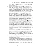
3. Automatic Electrode Contact Sensor/Switch Model TS101 --
Location
of
Internal
Indicators
and
Fuses
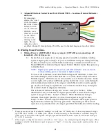
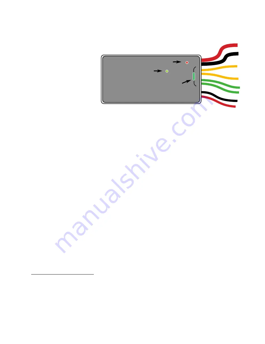
By removing 4
screws, the cover
of the Automatic
Electrode Contact
Sensor/ Switch
can be removed.
With the cover
removed, you will
see the objects
shown in the
drawing to the
right. The six
indicators which
Fuse
(2 amp)
Lamp #2
Lamp #1
are labeled Lamp #1 through Lamp #6 will be used in the fault diagnosis steps that follow.
B. Welding
Power
Problems
1. Welding
Power
is
ADJUSTABLE
but
power
output
is
LOW
6
OR power output drops off
immediately after striking an arc.
1.1
Insure that your engine is not loosing speed or is unable to maintain welding
speed at higher power settings. If you are unfamiliar with your welder, this may
be hard to detect by ear, but the built-in dual range tachometer circuit
7
in our
Model SCM.V2 Automatic Engine Speed Control Module makes this quite easy
to troubleshoot.
NOTE: Engine speed problems may not be noticeable until after an arc is struck,
or when welding power is increased to higher settings.
To access the tachometer, and other built in diagnostic indicators, remove the
four small Philips screws which hold the cover of the SCM.V2 Speed Control
Module in place. With the screws removed the cover should come free. If the
cover is tight, or if you have difficulty getting hold of the cover, a small straight
slot instrument screwdriver or the edge of a knife blade can be used to gently
pry on the cover edge to separate the cover from the module body and expose
the module’s built in diagnostic indicators.
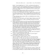
The tachometer indicator lamps are colored. Lamp 2 is Yellow. When
illuminated, Lamp 2 indicates an engine speed which is lower than the target
speed at any given time. Lamp 3 is Green. When illuminated, Lamp 3
indicates that engine speed is at, or near, ideal speed at any given time.
Lamp 4 is Red. When Lamp 4 is illuminated, it indicates that engine speed is
higher than the desired speed at any given time. Depending on the mode of
operation, at a particular time, the target speed that the indicators will be reading
6
Proper power output can be checked by making a test weld on a 1/4” thick piece of clean scrap material, using a
type 7018, 6011, or 6013 1/8” welding rod. The arc should start easily as the electrode is “scratched” along the
surface, and an acceptable welding bead with good penetration should be made with a Power Control setting of
2/3 to 3/4 of maximum.
7
When engine is idling the tachometer sets itself to a “low” range -- for reading/setting/checking idle speed. When
welding is initiated, the tachometer speed range goes to “high” -- for insuring proper engine speed/operation when
welding.


