background image


ZENAIR CH2000  SERVICE MANUAL 

________________________________________________________________________


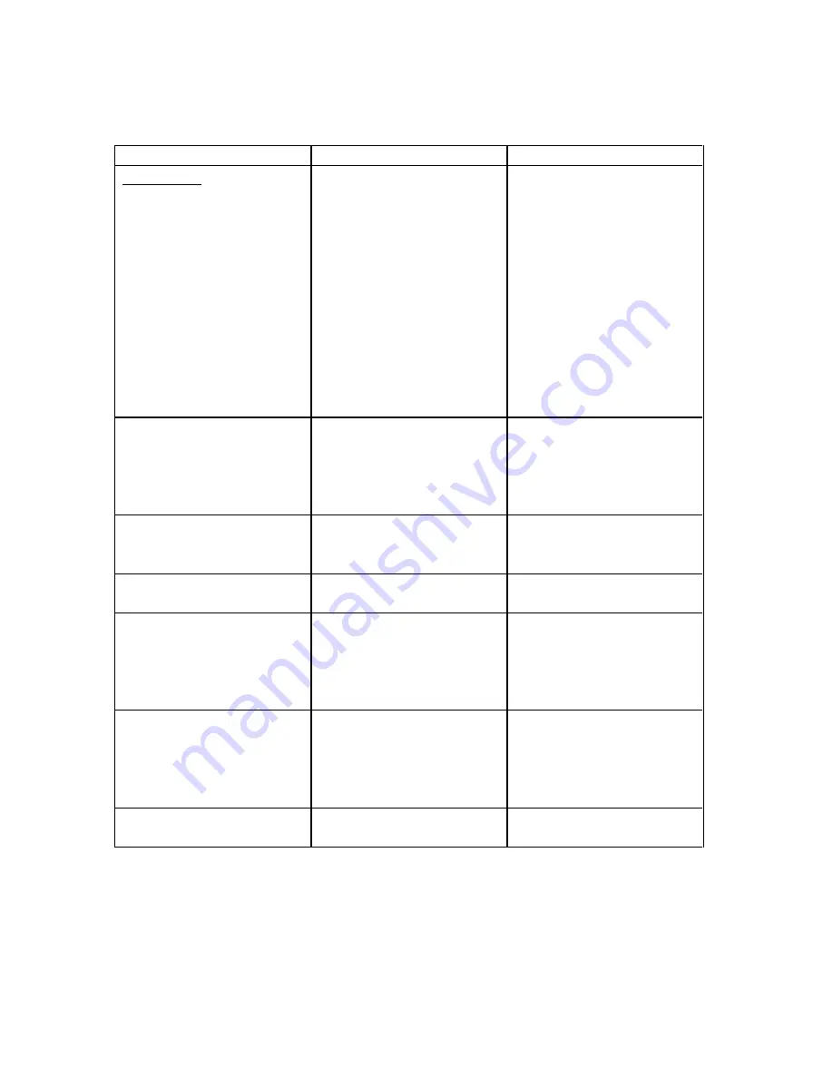
TABLE -  ELECTRICAL SYSTEM TROUBLESHOOTING 


Trouble 

Cause 

Remedy 

BATTERY 

 
Discharged battery. 


Battery worn out. 
Charging rate not set right. 
Standing too long. 
 
 
Equipment left on 
accidentally. 
Impurities in electrolyte. 
Short circuit (ground) in 
wiring. 
Broken cell partitions. 


Replace battery. 
Reset. 
Remove and recharge 
battery if left in unused 
airplane for too long. 
Remove and recharge. 
 
Replace electrolyte. 
Check wiring. 
 
Replace battery. 

Battery life is short. 

Overcharge due to level of 
electrolyte being below top 
of plates. 
Sulfation due to disuse. 
Impurities in electrolyte. 

Maintain electrolyte. 
 
 
Replace battery. 
Replace battery.  

Cracked cell jars. 

Hold-down bracket loose. 
 
Frozen battery. 

Replace battery and 
tighten. 
Replace battery. 

Excessive corrosion inside 
container. 

Spillage from overfilling. 
 

Use care in adding water. 
 

Battery freezes. 

Discharged battery. 
Water added and battery 
not charged immediately. 

Replace battery. 
Always recharge battery for 
1/2 hour following addition 
of water in freezing 
weather. 

Leaking battery jar. 
Battery polarity reversed. 

Frozen. 
Connected backwards on  
airplane or charger. 

Replace battery. 
Battery should be slowly 
discharged completely and 
then charged correctly and 
tested. 

Battery consumes 
excessive water. 

Cracked jar (one cell only).  Replace battery. 


3 Apr 95 


    10.7 

Summary of Contents for CH2000

Page 1: ...CH2000 TRAINER with LYCOMING 0 235 N2C SERVICE MANUAL ZENAIR Ltd Huronia Airport Midland Ontario Canada L4R 4K8 705 526 2871 November 2002...

Page 2: ...11 Apr 95 1 1 3 Apr 95 5 5 5 Nov 02 9 9 12 Apr 95 2 2 1 Apr 95 5 5 6 Nov 02 9 9 13 Apr 95 2 2 2 Oct 00 6 6 1 Feb 00 10 10 1 Apr 95 2 2 3 Nov 02 6 6 2 Nov 02 10 10 2 Oct 00 2 2 4 Nov 02 6 6 3 Apr 96 1...

Page 3: ..._____________________________________________________________ SERVICE MANUAL UPDATE LOG REV NO DATE ISSUED DATE INCORPORATED INSERTED BY 9 May 2011 May 2011 Note 0 1 and 0 2 with Update sheet s are re...

Page 4: ...ive maintenance and testing each major system of the aircraft is covered in a separate section Only qualified personnel should perform the operations described in this manual In the text reference is...

Page 5: ...d Lycoming Model 0 235 N2C four cylinder air cooled engine The engine employs a wet sump oil system with oil temperature and pressure indicators PROPELLER The propeller used is a Sensenich fixed pitch...

Page 6: ...ZENAIR CH2000 SERVICE MANUAL ________________________________________________________________________ CH 2000 GENERAL DIMENSIONS Fig 1 3 Apr 95 1 3...

Page 7: ...ls that provide access for purposes of service and maintenance GROUND HANDLING GENERAL The aircraft must not be pushed pulled or lifted by any other means than those described Procedures are given for...

Page 8: ...ZENAIR CH2000 SERVICE MANUAL ________________________________________________________________________ CH2000 ACCESS PANELS Fig 2 2 2 Oct 00...

Page 9: ...elage longeron To put the airplane in a longitudinally level position either on scales or on the floor deflate the nose wheel tire until the proper position is reached or add shims under the two main...

Page 10: ...CE MANUAL ________________________________________________________________________ LOCKING AIRCRAFT The cabin doors are provided with key locks on the outside MAIN GEAR WHEEL HOISTING NOSE GEAR WHEEL...

Page 11: ...ZENAIR CH2000 SERVICE MANUAL ________________________________________________________________________ AIRCRAFT LEVELING Fig 4 Oct 00 2 5...

Page 12: ...uld be in the OFF position when opening the Gascolator The Gascolator should be drained regularly to check for water REAR FUEL TANK SYSTEM The fuel tank and sump are drained through the Curtis valve b...

Page 13: ...ZENAIR CH2000 SERVICE MANUAL ________________________________________________________________________ FUEL DRAINS Fig 5 3 Apr 96 2 7...

Page 14: ...ction and replenished when necessary No adjustment of brake clearance is necessary on the brakes DRAINING BRAKE SYSTEM To drain the brake system disconnect the hydraulic brake lines from the brake ass...

Page 15: ...ZENAIR CH2000 SERVICE MANUAL ________________________________________________________________________ LUBRICATION CHART Fig 6 Feb 00 2 9...

Page 16: ...Limitation section is accepted by the FAA It can only be revised with prior FAA approval LIFE LIMITED PARTS Following is the list of the parts which must be replaced at the frequencies indicated Fuel...

Page 17: ...ribed in the Owner s Manual SCHEDULED INSPECTIONS Scheduled inspections include the items listed in Table 1 Inspection Form the overhaul requirements for the engine and propeller the calendar time ins...

Page 18: ...ed in seven groups Propeller Engine Cabin Landing Gear Wing Fuselage and Empennage The first column of Table 1 states the task to be performed the second column states the applicable references s The...

Page 19: ...st 5 Clean the spark plugs Adjust gap at 018 to 022 6 Check and set magneto timing at 20 0 7 Check magneto breaker points and lubricate breaker point felt 8 Clean oil suction and oil pressure screens...

Page 20: ...engine cowlings for cracks damage loose rivets etc 20 Inspect the vacuum pump lines and separator 21 Change the Oil filter 22 Inspect the oil radiator oil lines and attaching brackets 23 Clean and flu...

Page 21: ...nspect flight control turnbuckles pulleys and guides for wear damage and safeties 6 Check stabilator trim tab indicator for correct operation 7 Inspect the flap motor actuator extension tube actuator...

Page 22: ...rity condition etc 18 Inspect electrical wiring for condition security routing damage etc 19 Check condition and security of all bonding wires 20 Inspect antenna installations for condition security e...

Page 23: ...n leaks etc Service the master brake cylinders 7a Inspect the rubbers at the main landing gear attachments for condition and abrasion damage and position 8 When removing wheel the airplane hoisted rem...

Page 24: ...lubrication 4 Inspect flap and aileron rods and rod attachment bolts for wear damage safeties etc 5 Inspect aileron bellcranks stops cable ends and pulley assembly for cracks damage corrosion safetie...

Page 25: ...flight control cables for routing fraying corrosion and tension 4 Inspect flight control turnbuckles pulleys and guides for wear damage and safeties 5 Check flight control torque tube bearings for wea...

Page 26: ...500 1000 2 Inspect stabilator trim actuator wheel for security wear damage etc 3 Perform operational check of stabilator trim system 4 Inspect rudder stabilator and trim tab hinges for wear and excess...

Page 27: ...pe Zenair reference A 4 1 8 dia or A 5 5 32 dia to be set with the hand tool Zenair reference HP A4 A5 Aircraft quality aluminum Cherry rivets are an approved substitute Standard MS20470 rivets may be...

Page 28: ...nes left wing only 7 Disconnect the electric wirings 8 Remove the bolts on front and rear spar and the six main spar bolts 9 Pull the wing out REINSTALL the wing in reverse order of removal REPLACEMEN...

Page 29: ...61 T6 0 025 27 6061 T6 0 025 28 6061 T6 0 025 9 FIBERGLASS FIRE RESISTANT 29 FIBERGLASS 10 FIBERGLASS FIRE RESISTANT 30 6061 T6 0 016 11 6061 T6 0 025 31 6061 T6 0 016 12 6061 T6 0 025 32 6061 T6 0 03...

Page 30: ...CEMENT OF STABILATOR Fig 8 REMOVAL 1 Remove the rudder 2 Remove the side panels See 1 Fig 8 3 Remove the gap filler See 2 Fig 8 4 Remove the bolt at trim actuator and fork See 3 Fig 8 5 Disconnect the...

Page 31: ...ZENAIR CH2000 SERVICE MANUAL _______________________________________________________________________ TAIL REMOVAL Fig 8 Oct 00 4 5...

Page 32: ...and lower engine cowl 2 Hoist the airplane See Section II 3 Remove the upper stop plate 4 Disconnect the steering 5 Remove the shock ring from the forward upper support 6 Remove the lower front bearin...

Page 33: ...acket 20 L 3 3 when tightening Make sure that the rubber padding HH 16 top bottom are in place before tightening the four bolts REPLACEMENT OF MAIN WHEEL Fig 10 1 Hoist aircraft up 2 Remove the axle n...

Page 34: ...ZENAIR CH2000 SERVICE MANUAL ________________________________________________________________________ NOSE GEAR Fig 9 Nov 02 5 3...

Page 35: ...nd component parts to prevent damage during reassembly REASSEMBLE the master cylinder in the reverse order given for disassembly being careful not to damage the O rings Reinstall the master cylinder a...

Page 36: ...ZENAIR CH2000 SERVICE MANUAL ________________________________________________________________________ MAIN GEAR Fig 10 Older Style Main Gear Nov 02 5 5...

Page 37: ...ZENAIR CH2000 SERVICE MANUAL ________________________________________________________________________ BRAKE SYSTEM Fig 11 5 6 Nov 02...

Page 38: ...erforming any checks on the engine by connecting an electric wire from magneto terminal to the screw marked GD Ground on the magneto Refer to following paragraphs for procedures for removal and replac...

Page 39: ...ZENAIR CH2000 SERVICE MANUAL ________________________________________________________________________ POWERPLANT Fig 12 6 2 Nov 02...

Page 40: ...Place a tail stand under the tail of the aircraft before removing the engine 16 Check the engine for any attachments remaining to obstruct its removal 17 Remove the cotter pins nuts washers rear rubb...

Page 41: ...ZENAIR CH2000 SERVICE MANUAL ________________________________________________________________________ CARBURETOR Fig 13 6 4 Feb 00...

Page 42: ...3 4 4 and 5 8 MAGNETO TIMING If timing is required see Lycoming Manual pages 4 4 and 5 1 IDLE SPEED and MIXTURE ADJUSTMENT If idle RPM needs adjustment see Lycoming Manual page 5 7 for the procedure...

Page 43: ...Perform a functional check control rigging of the affected flight control system whenever re connection of the cables is completed Ref Figure 15 17 or 18 REMOVAL INSTALLATION OF AILERON CONTROL CABLES...

Page 44: ...OR CONTROL RIGGING Fig 17 1 Adjust cable tension to 40 lbs 5 2 With the stabilator trailing edge up on the stop check deflection limit 12 5 3 With the stabilator trailing edge down on the stop check d...

Page 45: ...the control rods 4 Open the fuselage access panel Fig 2 5 Disconnect the actuator lever by removing the four bolts on the interconnecting tubes and indicator cable liberating the actuator lever 6 Pul...

Page 46: ...ZENAIR CH2000 SERVICE MANUAL ________________________________________________________________________ AILERON AND CONTROLS Fig 15 7 4 Feb 00...

Page 47: ...ZENAIR CH2000 SERVICE MANUAL ________________________________________________________________________ FLAPS CONTROL SYSTEM Fig 16 Feb 00 7 5...

Page 48: ...ZENAIR CH2000 SERVICE MANUAL STABILATOR CONTROL SYSTEM Fig 17 7 6 Oct 00...

Page 49: ...ZENAIR CH2000 SERVICE MANUAL ________________________________________________________________________ RUDDER CONTROL SYSTEM Fig 18 Nov 02 7 7...

Page 50: ...ected to the easy drain beside the gascolator under the fuselage left side near the wing leading edge is the fuel tank sump The fuel valve is of the ON OFF position type REPLACEMENT OF REAR TANK 1 Dra...

Page 51: ...g tanks option verify that the fuel lines cross over behind the spar as illustrated on Fig 20 FINGER SCREENS Fig 19 and Fig 20 The finger screens are easily accessible at the tank outlet 1 Drain the t...

Page 52: ...ll Incomplete ground Check ground connections at fuel transmitter No fuel pressure indication Fuel valve stuck No fuel in tanks Defective fuel pump Defective gauge Check valve Check fuel fill Check pu...

Page 53: ...ZENAIR CH2000 SERVICE MANUAL ________________________________________________________________________ STANDARD FUEL SYSTEM REAR TANK Fig 19 8 4 3 Apr 96...

Page 54: ...ZENAIR CH2000 SERVICE MANUAL OPTIONAL FUEL SYSTEM WING TANKS Fig 20 3 Apr 96 8 5...

Page 55: ...PEED INDICATOR GENERAL The airspeed indicator provides a means of indicating the speed of the airplane passing through the air The airspeed indication is the differential pressure reading between dyna...

Page 56: ...ZENAIR CH2000 SERVICE MANUAL INSTRUMENT PANEL Note Position of optional instruments may vary according to owner s specifications Fig 21 9 2 Oct 00...

Page 57: ...t Setting knob set screw loose or missing Excessive vibration Tighten instrument screw if loose Replace instrument if screw is missing Cracked or loose cover glass Excessive vibration Replace instrume...

Page 58: ...ror Compass not properly compensated External magnetic interference Compensate instrument Locate magnetic interference and eliminate if possible Excessive oscillation Improper mounting on instrument p...

Page 59: ...ft Excess friction in instrument Repair or replace Replace instrument ENGINE OIL PRESSURE GAUGE GENERAL The oil pressure gauge is mounted in the cluster on the instrument panel This gauge will indicat...

Page 60: ...Dull or discolored luminous marking Age Replace instrument FUEL QUANTITY INDICATOR GENERAL The fuel quantity gauge s used on the CH2000 is are mounted in the cluster on the instrument panel These inst...

Page 61: ...heck diaphragm and relief valves in engine pump Check for obstruction in electric pump Replace gauge sender Pressure low or pressure surges Obstruction in inlet side of pump Faulty bypass valve Faulty...

Page 62: ...r fails to respond Obstruction in static line Disconnect all instruments connected to the static line Check individual instruments for obstruction in lines Pointer oscillates Leaks in static lines Def...

Page 63: ...No vacuum pressure gauge indication at instrument Hose from instrument to gauge leaking or restricted Check all lines and connections No vacuum suction gauge indication at either instrument or source...

Page 64: ...and the instrument case is shown on the instrument dial which is similar to a compass card The dial when set to agree with the airplane magnetic compass provides a positive indication free from swing...

Page 65: ...ZENAIR CH2000 SERVICE MANUAL ________________________________________________________________________ GYRO SYSTEM OPTIONAL Fig 22 3 Apr 95 9 11...

Page 66: ...table GYRO HORIZON INDICATOR Trouble Cause Remedy Bar fails to respond Insufficient vacuum Check pump and tubing Bar does not settle Excessive vibration Check shock mounts Replace if necessary Insuff...

Page 67: ...w Broken or loose cover glass Vibration or excessive pressure Replace glass and reseat case Dull or discolored luminous markings Age Replace instrument Incorrect reading Moisture or oil in line Discon...

Page 68: ...truments controls the battery relay The master switch must be on before any electrical equipment will operate The CH2000 can be equipped with the standard navigation lights strobes and dual landing li...

Page 69: ...ZENAIR CH2000 SERVICE MANUAL _______________________________________________________________________ ELECTRIC SCHEMATICS Fig 23 10 2 Oct 00...

Page 70: ...ZENAIR CH2000 SERVICE MANUAL ________________________________________________________________________ ELECTRIC WIRING Fig 24 Oct 00 10 3...

Page 71: ...cold weather cranking capacity All connections must be clean and tight If battery is not up to normal charge recharge starting with a charging rate of 4 amperes and finishing with 2 amperes The normal...

Page 72: ...eter indicates a heavy discharge with engine off or the alternator breaker off when the master is on the diodes in the alternator are shorted repair or replace the alternator For procedures and specif...

Page 73: ...ll of the wing If the buzzer does not operate when lifting the contact check the contact the buzzer and the breaker for proper operation The contact element on the wing leading edge is replaced by rem...

Page 74: ...ing below top of plates Sulfation due to disuse Impurities in electrolyte Maintain electrolyte Replace battery Replace battery Cracked cell jars Hold down bracket loose Frozen battery Replace battery...

Page 75: ...eed Worn rough or improperly lubricated motor or starter gearing Same electrical causes as listed under Motor fails to operate Disassemble clean inspect and relubricate replacing ball bearings if worn...

Page 76: ...onnect the hoses of the cabin heat shroud 2 Remove the heat shroud and inspect the outer surface of the inner core exhaust pipe for signs of combustion products 3 Thoroughly clean the exhaust pipe of...

Page 77: ...ZENAIR CH2000 SERVICE MANUAL _______________________________________________________________________ CABIN HEAT AND VENTILATION Fig 25 11 2 Nov 02...

Page 78: ...ke sure that it is not worn through that it rotates freely and that it is greased The schematic shows a 10 32 rivnut located front rear of each door with washers and countersunk screw When the door ha...

Reviews: