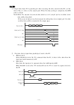
background image

-  21  -


5.4.3. T command 


Function 

  Output the pulse to control signal “TRG”.


Format 

CR LF


Return value 

OK 

CR LF

: 

Pulse output is completed. 

HG 

CR LF

: 

Pulse output error. 

5.4.4. C command 


Function 

  Output the pulse to control signal “CLR”.


Format 

CR LF


Return value 

OK 

CR LF

: 

Pulse output is completed. 

HG 

CR LF

: 

Pulse output error. 


5.4.5. D command 


Function 


Set the I/O of the four ports. All four ports are set to input when powering on the 
ZS-6222.


Format 

Dxxxx 

CR LF

: 

Make setting in the order of port_1, port_2, port_3, and port_4 after 

“D”. “x” is writes “I” for input, “O” for output. 


Return value 

OK 

CR LF

: 

Setting is completed. 

HG 

CR LF

: 

Setting error, wrong character setting. 


5.4.6. P command 


Function 

  The  pulse  width  of  the  control  signal  “STB”,  “TRG”,  “CLR”  can  be  set  from  10µs, 

100µs, 1ms. It is set to 10µs when powering on the ZS-6222.


Format 

P


CR LF

: 

“x” is 0 for 10µs, 1 for 100µs, 2 for 1ms. 


Return value 

OK 

CR LF

: 

Setting is completed. 

HG 

CR LF

: 

Setting error, wrong character setting. 


5.4.7. L command 


Function 

  It is possible to set the presence or absence of the latch circuit when inputting data. 
    It is set without latch circuit when powering on the ZS-6222.


Format 

L


CR LF

: 

“x” is 0 for absence, 1 for presence. 


Summary of Contents for ZS-6222 Series

Page 1: ...1 ZS 6222 Series USB PIO Adapter User s Manual Zip code 183 0027 2 13 37 Honmachi Fuchu Tokyo Japan TEL M81 0 42 368 2126 FAX M81 0 42 364 0067 URL http www zenisu co jp...

Page 2: ...pearance 4 4 Install 5 4 1 Download device driver 5 4 2 Windows Vista 5 4 3 Windows XP 2000 12 5 Operation 17 5 1 Transfer data method 17 5 2 Control signal 18 5 3 I O 19 5 4 Command chart 20 5 4 1 R...

Page 3: ...Output Bidirectional data 4 Byte 3 2 Bit 2 Feature It is possible to be easily controlled with a laptop computer There are 4 ports 8bits port for parallel signals and I O can be selected with each po...

Page 4: ...in type Data connector 50 coreflat cable 50 core flat cable Power supply DC4 75V to 5 25V 100mA or less DC4 75V to 5 25V 100mA or less Environment Tempreture0 to 50 Humidity85 or less Tempreture0 to 5...

Page 5: ...ary to install hardware and device driver by following procedure at first Turn on the power to the PC and start Windows Connect this product and PC with a USB cable Install the device driver Complete...

Page 6: ...6 Click Try other method Click Search the computer for driver software...

Page 7: ...7 Refer to the downloaded file and click HEXT button It is displayed Issuer of driver software can not be verified but there is no problem Click Install this driver software...

Page 8: ...8 Click Close button The following screen will be displayed Click Search and install driver software...

Page 9: ...9 Click Try other method Click Refer to the computer and search for driver software...

Page 10: ...10 Refer to the downloaded file and click HEXT button It will be displayed but there is no problem Click Install this driver software...

Page 11: ...11 Click Close button...

Page 12: ...he PC and start Windows 2 Connect this product and PC with a USB cable 3 Install the device driver 4 Complete the installation Device driver installation method is explained below The following screen...

Page 13: ...location refer to the downloaded driver and click HEXT button The following screen will be displayed Only for XP It is displayed It has not passed Windows logo test to verify compatibility with Window...

Page 14: ...be asked to reboot according to the configuration of the PC In that case restart according to the instructions on the screen The following screen will be displayed Select Install from the list or spe...

Page 15: ...15 Select Search for the driver in the following location refer to the downloaded driver and click HEXT button There is no problem click Continue button...

Page 16: ...16 Click Finish button After that it may be asked to reboot according to the configuration of the PC In that case restart according to the instructions on the screen...

Page 17: ...umber and the value differs depending on the personal computer When creating a program please open it according to the displayed COM number Data code The data transfer method is used ASCII code and on...

Page 18: ...0 1101 D7 D0 C D 1 2 3 4 ZS 6222 Input Output 0123 ABCD 5 2 Control signal A control signal is displayed so that it can be synchronized with the connected device Signal Direction Description STB OUT Z...

Page 19: ...port the data sent last time will be remained in the empty space Received data 1 3 2 4 Output port_3 High Low High Low Output port_4 STB output 1 2 3 4 The data that is input from parallel port send t...

Page 20: ...n Data is read from all ports set as input e g If input port is set four ports 8 bytes of data will be sent from ZS 6222 when R command is used Format R CR LF Return value xxxx CR LF Amount of data as...

Page 21: ...t_1 port_2 port_3 and port_4 after D x is writes I for input O for output Return value OK CR LF Setting is completed HG CR LF Setting error wrong character setting 5 4 6 P command Function The pulse w...

Page 22: ...19 20 D1 D2 21 22 D2 PORT D3 23 24 D3 PORT D4 25 26 D4 D5 27 28 D5 D6 29 30 D6 D7 31 32 D7 IN LAH 33 34 NC OUT STB 35 36 NC OUT TRG 37 38 NC OUT CLR 39 40 NC NC 41 42 GND NC 43 44 GND NC 45 46 GND NC...

Page 23: ...ith instruction manual 2 It will be charged for extra in the following case even during warranty period Incorrect usage or failure or damage caused by carelessness Failure or damage caused by improper...

Reviews: