12
EA1400/1600 Installation & User Manual
A100K11939
The speakers must be connected in parallel. The impedance taps on the primary of the line transformers
determine the power taken from the line. One or more speakers may be removed or added without
affecting the rest of the system.
Speakers are added as needed until the total wattage absorbed by the line transformers is equal to the
rated output power of the amplifier. It is good practice to give a power headroom of 10% - 20%, i.e. a
speaker load of 500W on a 600W amplifier.
Example
:
To calculate the maximum number of 30W speakers on a 600W amplifier:
Number of speakers = Amplifier power / Speaker power = 600/30 = 20
3.8. Optional Connections
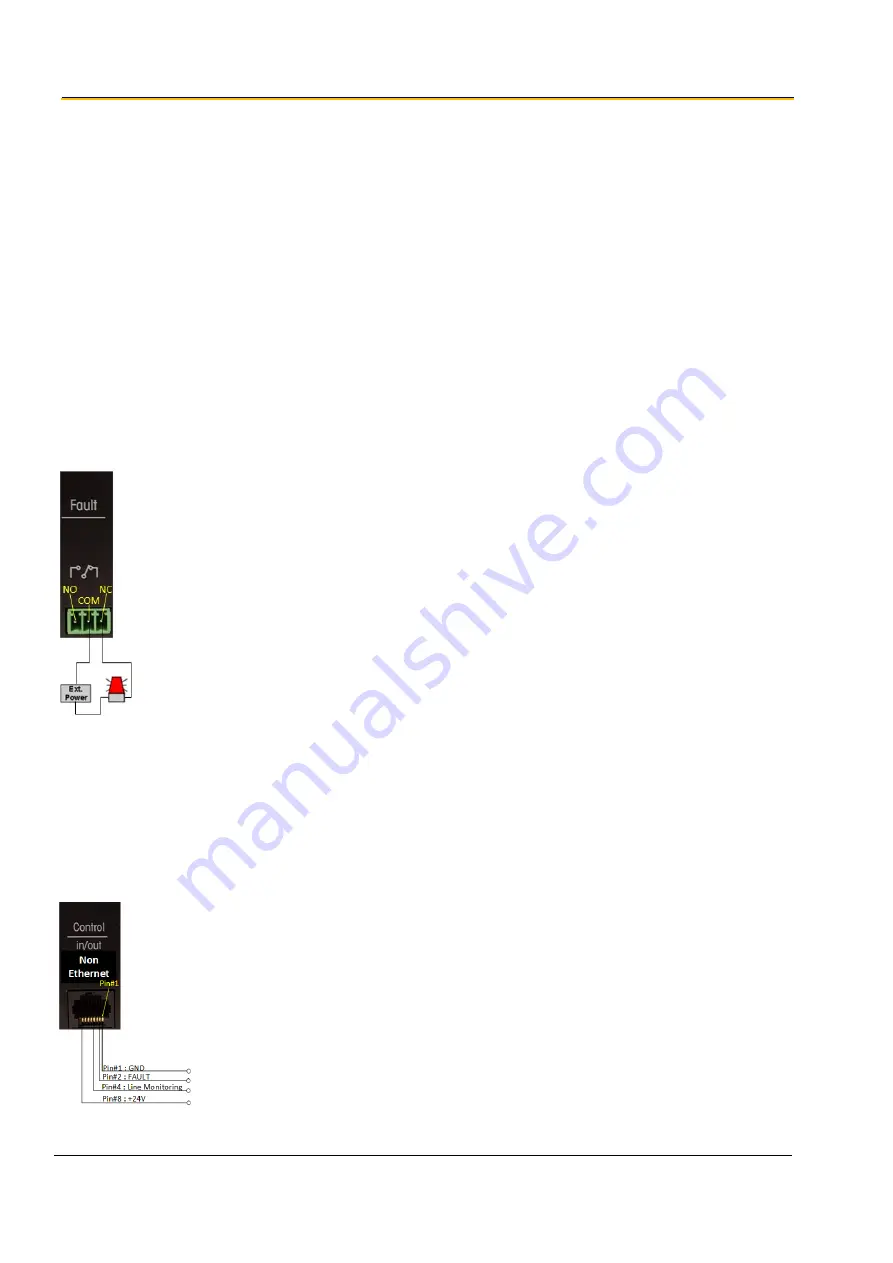
Fault Relay
Connect one wire from an external warning device to the FAULT RELAY terminal marked COM.
Insert a suitable power supply between the other device wire and the NC terminal.
The relay contacts can switch up to 1 A at 24 VDC.
EXT I/O Control


