4-8
Configuring Your System
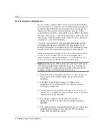
ISA Board Configuration
If you want to add an ISA board to your system that is
not included in a .cfg file, use the following procedures
to define and add the option board. It is necessary to
define an ISA board to prevent other boards in the
system from using the same IRQ levels, DMA channels,
I/O port addresses, or memory addresses, that your ISA
board uses. Standard ISA board options have .cfg files
already on your SCU diskette.
You must run the SCU and add the ISA board to the
configuration before installing the ISA board in the
system, otherwise the resources on the ISA board may
conflict with a Plug-and-Plug board in the system.
BIOS automatically assigns ISA Plug-and-Plug boards
to the next available slot. If the slot displayed in
Step 2: “Add or Remove Boards” is not the actual slot,
it can be moved by using the F7 function key.
Notice: IRQ levels, DMA channels, I/O port addresses,
and memory addresses defined using this procedure
should reflect the same settings defined by supplied
jumpers and/or configuration documents.
1. Insert the SCU diskette into drive A: and power-on
the system. The system boots-up using the SCU
diskette.
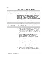
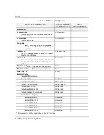
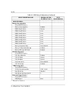
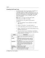
2. The SCU Main Menu shown in Table 4-1 is
displayed. At the Startup Menu, enter choice 2,
Configure Computer.
3.
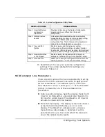
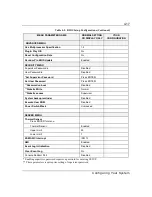
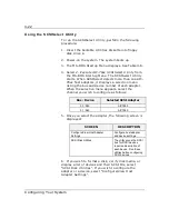
The System Configuration Utility Menu shown in
Table 4-2 is displayed. Select Step 2 Add or Remove
Boards and press ENTER.
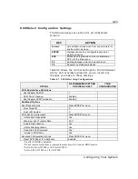
4. The Step 2: Add or remove boards screen is
displayed. At this screen select Add by pressing
INSERT.
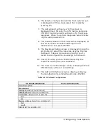
5. The Add screen is displayed telling you to locate the
diskette that contains the .cfg file for the board.
Press ENTER at this screen.
Summary of Contents for MT2000
Page 1: ...Server MT2000 U s e r s G u i d e...
Page 6: ...raham...
Page 8: ...Bill Graham...
Page 9: ...Chapter 1 Introduction Contents Organization 1 Notational Conventions 3...
Page 10: ...Bill Graham...
Page 53: ...1231231 Billy Graham...
Page 81: ...4 28 Configuring Your System Figure 4 2 System Board Jumpers...
Page 141: ...5 53 Upgrades and Options Figure 5 25 Removing the Rear Fan modules...
Page 143: ...dfgdfg...
Page 171: ...Bill GrahamBill Graham...
Page 182: ...Appendix B Memory Configurations Contents Memory DIMM Configurations 1...
Page 183: ...Bill Grahamaerrterterter...
Page 186: ...Appendix C Option Boards Contents Introduction C 1...
Page 188: ...Appendix D Devices Contents Introduction 1...
Page 190: ...Appendix E Network Operating Systems Contents Introduction 1...
Page 193: ...rtyrtyrtyrtyry...
Page 203: ...8 Glossary...
Page 204: ......
Page 205: ...101843 1...

