HIGH VOLTAGE AND X-RADIATION PROTECTION
A potential source of x-rays is the picture tube, if the high
voltage (HV) is out of specification. When the HV is operating
properly, there is no x-radiation. For the CA chassis family,
the HV has no adjustments. A HV shutdown circuit is used to
prevent excessive HV and x-ray emissions.
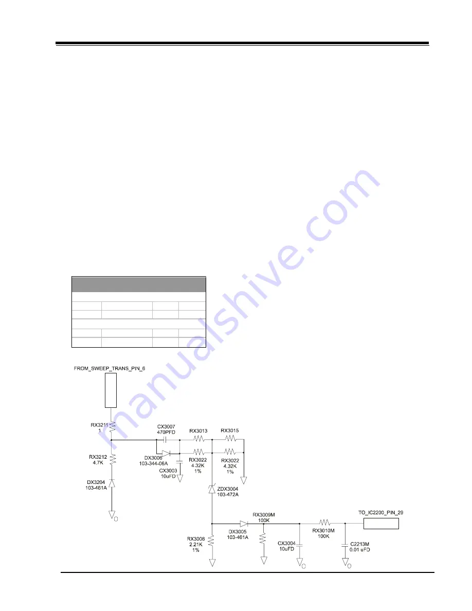
THEORY OF OPERATION (SHUTDOWN CIRCUIT)
This circuit basically monitors the sweep pulse voltage de-
rived from the sweep transformer TX3204 pins 5 & 6. This
voltage is rectified, and applied to a 12V zener diode ZDX3004.
When the HV reaches its maximum allowed ,value (see draw-
ing) the zener diode conducts, the voltage on pin 29 of the
video processor (ICX2200) increases until it reaches the thresh-
old voltage of 3.5 VDC, and shuts down the TV. If the shut-
down circuit has operated, the microcontroller will prevent
the TV from being turned on again, without first having to
unplug the AC cord to reset the microcontroller.
TIP:
Make a momentary short between the OUTPUT and GND
of the IC6002 (RESET CIRCUIT) this will reset the microcontroller
IC6000. Apply signal through the video generator or tune the
TV color receiver to crosshatch pattern. Connect an accurate
HV meter between the picture tube anode and chassis ground.
Access Video Menu and adjust Brightness and Contrast con-
trols for minimum screen luminance. Wait until, the Video
Menu or display disappear. Read HV meter.
SAFETY CIRCUIT TEST PROCEDURE
Equipment required:
a) Video Generator.
b) HV DC meter (0 to 40 KV, high Z).
c) External variable power supply (0V to 200 VDC @ 5Amps
minimum).
d) 1 Giga ohm, 5%, 2W film resistor.
Before turning the TV on, connect the HV meter’s negative
probe (-) to ground (DAG ground recommended) and the posi-
tive probe (+) in the anode of the CRT. Connect a 1 Giga Ohm
resistor in parallel with the HV meter. Then connect the exter-
nal power supply’s negative output (-) to chassis ground, that
is, the negative lead of B+ filter capacitor, CX3420. Turn on
the TV. Apply a video signal or tune the TV to a raster pattern.
Adjust the G2 potentiometer for minimum, and set the bright-
ness and contrast levels to minimum. Now adjust the output
voltage of the external power supply to 124 VDC for CA25V/
27V or 130 VDC for CA32V/36V. Then start increasing the
voltage on the external power supply until the TV shuts down,
and read the HV on the meter just before the voltage starts
dropping.
Note: The external power supply may require a diode for
blocking voltage from the chassis power supply to
the external power supply. The diode should be
connected between the positive output of the external
power and B+ of the chassis. The cathode should be
facing the B+ of the chassis. The recommended diode
is Part No. 103-00339-04A (400 V of VRRM @ 3
Amps of average rectified forward current).
SCREEN
B+ VDC
HV NOM HV MAX
SIZE
(0 BEAM)
KV
KV
25
124.0 +/- 2%
28
29
27
124.0 +/- 2%
27
29
32
128.5 +/- 2%
30
31.5
36
128.5 +/- 2%
30
31.5
MODULE LEVEL REPAIR ONLY
COMPONENT LEVEL REPAIR
PRODUCT SAFETY SERVICING GUIDELINES FOR AUDIO-VIDEO PRODUCTS
ii
CM151
CA - SAFETY


