background image

206-3481

P A G E   4

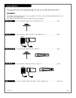
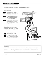
(Continued from previous page)

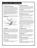
14. Outdoor Antenna Grounding

If an outside antenna or cable system is connected to the
product, be sure the antenna or cable system is grounded
so as to provide some protection against voltage surges
and built-up static charges. Article 810 of the National
Electrical Code (U.S.A.), ANSI/ NFPA 70 provides 
information with regard to proper grounding of the mast
and supporting structure, grounding of the lead-in wire to
an antenna discharge unit, size of grounding conductors,
location of antenna-discharge unit, connection to 
grounding electrodes, and requirements for the grounding
electrode.

15. Lightning

For added protection for this product (receiver) during a
lightning storm, or when it is left unattended and unused
for long periods of time, unplug it from the wall outlet and
disconnect the antenna or cable system. This will prevent
damage to the product due to lightning and power-line
surges.

16. Power Lines

An outside antenna system should not be located in the
vicinity of overhead power lines or other electric light or
power circuits, or where it can fall into such power lines or
circuits. When installing an outside antenna system,
extreme care should be taken to keep from touching such
power lines or circuits as contact with them might be
fatal.

17. Overloading

Do not overload wall outlets and extension cords as this
can result in a risk of fire or electric shock.

18. Object and Liquid Entry

Never push objects of any kind into this product through
openings as they may touch dangerous voltage points or
short-out parts that could result in a fire or electric shock.
Never spill liquid of any kind on the product.

19. Servicing

Do not attempt to service this product yourself as opening
or removing covers may expose you to dangerous voltage
or other hazards. Refer all servicing to qualified service
personnel.

20. Damage Requiring Service

Unplug this product from the wall outlet and refer servic-
ing to qualified service personnel under the following 
conditions:

a. If the power-supply cord or plug is damaged.

b. If liquid has been spilled, or objects have fallen into

the product.

c. If the product has been exposed to rain or water.

d. If the product does not operate normally by following

the operating instructions. Adjust only those controls that
are covered by the operating instructions as an improper
adjustment of other controls may result in damage and will
often require extensive work by a qualified technician to
restore the product to its normal operation.

e. If the product has been dropped or the cabinet has

been damaged.

f. If the product exhibits a distinct change in 

performance.

21. Replacement Parts

When replacement parts are required, be sure the service
technician has used replacement parts specified by the
manufacturer or have the same characteristics as the 
original part. Unauthorized substitutions may result in fire,
electric shock, or other hazards.

22. Safety Check

Upon completion of any service or repairs to this product,
ask the service technician to perform safety checks to
determine that the product is in proper operating 
condition.

23. Wall or Ceiling Mounting

The product should be mounted to a wall or ceiling only as
recommended by the manufacturer.

24. Heat

The product should be situated away from heat sources
such as radiators, heat registers, stoves, or other products
(including amplifiers) that produce heat.

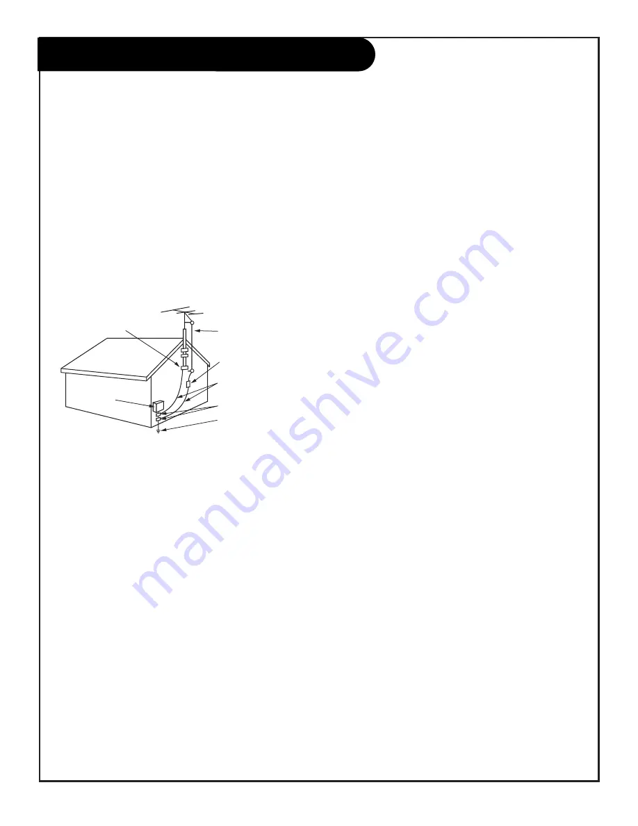
Antenna Lead in Wire

Antenna Discharge Unit
(NEC Section 810-20)

Grounding Conductor
(NEC Section 810-21)

Ground Clamps

Power Service Grounding
Electrode System (NEC
Art 250, Part H)

Ground Clamp

Electric Service

Equipment

Example of Grounding According to National Electrical
Code Instructions

NEC - National Electrical Code

IMPORTANT SAFETY INSTRUCTIONS

Summary of Contents for B27A34Z

Page 1: ...machine numbers B27A34Z B32A34Z B36A34Z o p e r a t i n g g u i d e w a r r a n t y h o o k u p d i r e c t o r y g l o s s a r y y o u r o n s c r e e n m e n u s p a g e 48 p a g e 18 p a g e 6...

Page 2: ...o Part 15 of the FCC Rules These limits are designed to provide reasonable protection against harmful interference when the equipment is operated in a residential installation This equipment generates...

Page 3: ...ufacturer s instructions and should use a mounting accessory recommended by the manufacturer 8 Transporting Product A product and cart combination should be moved with care Quick stops excessive force...

Page 4: ...you to dangerous voltage or other hazards Refer all servicing to qualified service personnel 20 Damage Requiring Service Unplug this product from the wall outlet and refer servic ing to qualified ser...

Page 5: ...On Off Timer 25 Channel Labels 26 XDS Display 27 Parental Control 28 29 EZ Demo On screen menus overview 30 Audio Menu 31 Bass Treble Balance Audio Mode Front Surround EZ Sound Rite Speakers EZ Sound...

Page 6: ...he appropriate page for hook up your Entertainment MachineTM IMPORTANT Use this page to decide where you need to begin your setup First find the line below that best describes what you want to do then...

Page 7: ...r antenna to your Entertainment MachineTM Hook up your Entertainment MachineTM see diagrams at right Remove the back of the remote and put in two AAA batteries Plug in your TV Do not plug it into a sw...

Page 8: ...ns Cable TV wall jack Cable TV wall jack Cable box In Out RF coaxial wire 75ohm RF coaxial wire 75ohm 3 4 output switch TV back panel expanded view Antenna Cable TV back TV back panel expanded view An...

Page 9: ...ideo Out 3 4 VCR back VCR back A V panel In Out 3 4 VCR back VCR back A V panel Flat wire 300 ohm Antenna 300 75 ohm Adapter Round wire 75ohm Antenna output switch output switch A V cables not include...

Page 10: ...75ohm not included with TV In Out Audio R L Out Video Out 3 4 VCR back VCR back A V panel In Out 3 4 VCR back VCR back A V panel output switch output switch A V cables not included with TV A V cables...

Page 11: ...to TV jack to the Antenna Cable jack on the back of your TV Find the audio and S Video jacks on the back of your S VHS VCR and connect them following the instructions provided with your equipment 1 2...

Page 12: ...for the stereo system Connect the stereo system s cables according to their color red is the right channel white the left to these jacks 1 Before you begin plugging in your stereo system it s a good i...

Page 13: ...Surf EZ Clock Captions Caption Text Language To Program 123 7 3 5 1 206 3481 Note EZ Program finds channels being received by the TV tuner See page 17 for instructions on using the Cable Box or VCR t...

Page 14: ...r channel num bers for instant selection NUMBER KEYPAD Selects channels directly and enters numeric values for some options MENU Shows on screen menus for TV mode See page 18 UP DOWN ARROWS The Up Dow...

Page 15: ...1 2 3 4 5 Use either the remote or the TV front controls to access the on screen menus Setup Menu EZ Program Add Del Surf EZ Clock Captions Caption Text Language EZ Mute 123 On screen menus automatic...

Page 16: ...the selected feature using the LEFT or RIGHT Volume buttons Note If the feature you want to change requires you to enter numerical values use the remote control Menus disappear after fifteen seconds...

Page 17: ...me display will read Video in place of a channel number if A V inputs are selected as the picture source Antenna Cable Input This setting allows you to change cable or antenna channels and to view vid...

Page 18: ...description below Adv TV Control 28 Allows parents to block any program or A V source for up to 99 hours with the use of a password EZ Demo 30 Demonstrates the on screen menus that control TV setup an...

Page 19: ...lay Sleep Timer Display Press TIMER on the remote control to view the Sleep Timer Status Display Press TIMER repeat edly to set the amount of time before the TV automatically turns itself off Remove O...

Page 20: ...your channel selection Press MENU repeatedly on the remote until the Setup menu appears Select the Add Delete Surf option with the UP or DOWN arrow Using either the NUMBER keypad and ENTER or the CHAN...

Page 21: ...y on the remote until the Setup menu appears Highlight the EZ Clock option using the Select UP or DOWN arrow Using the Adjust LEFT or RIGHT arrow select Manual or Automatic mode Time Set Using either...

Page 22: ...llowing options Caption 1 Caption 2 Caption 3 Caption 4 Text 1 Text 2 Text 3 or Text 4 Press QUIT to return to TV viewing Caption Text is a feature which allows your Entertainment MachineTM to receive...

Page 23: ...enu EZ Programa Agr Bor Surf Ajuste Reloj Subt t Subt t Texto Language Spanish 123 1 2 3 4 Press MENU on the remote control repeatedly until the Setup menu appears Use the UP or DOWN arrow on the remo...

Page 24: ...enu Select Sleep Timer using the UP or DOWN arrow Use the RIGHT or LEFT arrow to choose from the preset times the time you want the TV to turn itself off you can choose a time period from 10 minutes t...

Page 25: ...and select an off time On Off Timer Use the UP or DOWN arrow to select the On Off Timer option Use the LEFT or RIGHT arrow to set the On Off Timer to either On TV will turn on and off automatically O...

Page 26: ...o select CH LABELS Select a label for the channel Press the RIGHT arrow key each press will bring up a different label to go through the alpabetical listing starting with A B C D etc Or use the LEFT a...

Page 27: ...PIP is active the PIP channel number Use the Extended Data Service to show in depth program information 1 2 3 4 Press MENU on the remote repeatedly until the Special Features menu appears Highlight th...

Page 28: ...lock program Content based on individual parameters such as Strong Dialog Bad Language Sex Scenes Violence Scenes or Fantasy Violence Scenes in the Content Blk option How many hours do you want Parent...

Page 29: ...he Mini Glossary Ratings Charts on this and the previous page for rating meanings Use the UP or DOWN arrow to select another Content Block classification like Language for example and then choose an a...

Page 30: ...G E 3 0 Press MENU repeatedly on the remote control until the Special Features menu appears Use the Up or Down arrow on the remote control to select EZ DEMO on your screen Press the RIGHT or LEFT arr...

Page 31: ...rogramming is broadcast in stereo sound or has Second Audio Programming SAP If 2nd Audio SAP is selected and none is present audio may not be heard Bass Increase decrease lower end sounds Treble Incre...

Page 32: ...fter the image will appear Color Temp Adjust the color qualities of the entire picture at once options are warm and cool EZ Picture Choose appropriate viewing setting based on the video image provided...

Page 33: ...select an option on your screen Use the RIGHT or LEFT arrow to change the option Press QUIT to return to TV viewing Color Adjusts the color of the PIP inset Tint Adjusts the relative amounts of the re...

Page 34: ...original picture sources If you connected component s to the S Video In jacks then the Source menu will show S Video 1 S Video 2 etc as the available sources instead of Video 1 and Video 2 P A G E 3...

Page 35: ...e to take its image from Set the main screen source to Antenna Cable then set the PIP source to Video 1 as an example Choose your PIP and Main Screen sources using the Source menu PIP can be used in a...

Page 36: ...reeze the image in the PIP inset press FREEZ again to resume motion WITH PIP ON OPERATIONS PIP Swap Use the UP or DOWN arrow to switch the PIP inset image with the main picture Channels Press CHANNEL...

Page 37: ...or the S Video 2 input S VHS 1 or S VHS 2 will appear as available sources instead of Video 1 or Video 2 If no equipment is connected to a source you select for the PIP inset or if it is turned Off th...

Page 38: ...8 5 3 Turn on the device you want to program On the chart on page 42 43 find the type of device you re programming and then find the brand name Make a note of the three number code you ll need it soon...

Page 39: ...OWER VOLUME VOLUME QUIT CC FFWD TV VCR SOURCE 2 5 3 4 Indicator Light Find the code that operates your amplifier Test it to make sure it s the correct one by following the procedure in Programming You...

Page 40: ...Programming your Zenith remote may allow you to use one remote to work up to 7 different products or devices Some devices may not work with your Zenith remote control P A G E 4 0 3 Refer to the chart...

Page 41: ...ANNEL CHANNEL 1 2 3 4 5 6 7 0 8 9 MENU REWIND RECORD PIP SWAP FREEZ PAUSE TIMER PLAY STOP SURF MUTE POWER VOLUME VOLUME QUIT CC FFWD TV VCR SOURCE TV Turn on the device you want the remote to control...

Page 42: ...ha 202 218 Zenith 201 224 225 229 237 Admiral 116 121 130 133 Adventura TV VCR 154 Akai 104 Amark 103 146 AOC 104 Bell Howell 121 Broksonic 131 136 Candle 139 Centurion 119 Citizen 121 139 Contec 141...

Page 43: ...Pioneer 402 403 Sanyo 401 Sony 404 Zenith 401 Akai 409 424 Crown 410 Denon 411 Fisher 412 438 Goldstar 460 Harman Kardon 413 JVC 415 Kenwood 412 416 417 441 Magnavox 421 422 433 434 Mitsubishi 423 424...

Page 44: ...it 4 AUX Digit 4 5 TV Digit 5 VCR Digit 5 Cable Digit 5 AUX Digit 5 6 TV Digit 6 VCR Digit 6 Cable Digit 6 AUX Digit 6 7 TV Digit 7 VCR Digit 7 Cable Digit 7 AUX Digit 7 8 TV Digit 8 VCR Digit 8 Cable...

Page 45: ...er and polish This will protect the Entertainment MachineTM from dirt and dust as well as keep the cabinet looking new If you leave your Entertainment MachineTM dormant for a long time such as a vacat...

Page 46: ...be the broadcast not your Entertainment MachineTM Are the Audio A V cables properly installed Are you in TV or cable tuning mode and should be in the other Make sure output channels on all A V equipm...

Page 47: ...ntinue to appear Try unplugging your Entertainment MachineTM for a few minutes then plug it back in Don t forget to reset the clock Check to see if the source equipment has been turned on Make sure th...

Page 48: ...pment that the remote control is currently controlling TV VCR Cable etc is the remote s operating mode MONO SOUND Mono monaural sound is one channel of sound On more than one speaker all the speakers...

Page 49: ...Notes...

Page 50: ...Notes...

Page 51: ...ble on your Satellite sys tem Perfect backup antenna for cable outages Enhanced quality picture and stereo sound in weak signal areas Amplified VHF UHF FM Antenna includes 4 feet of 75 ohm cable for e...

Page 52: ...evidence of the purchase date Operating Guide Read your Operating Guide carefully so that you will understand the operation of your set and how to adjust the customer controls Carry In Service Models...

Reviews: