P A G E 1 9
206-3643
VIDEO
ANTENNA
CABLE
R- AUDIO- L
S-VIDEO IN
COMPUTER
AUDIO
R
L
AUX IN
M.P.I.
TV back
R- AUDIO- L
R- AUDIO- L
S-VIDEO OUT
AUDIO OUT
Video Out
C
O
M
P
U
T
E
R
I
N
S-Video cable
not included
with TV
Audio Out
S-Video Out
3 4
VCR back
VCR back AV panel
output
switch
R L
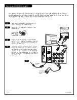
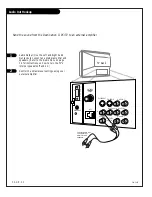
Connect Audio Out
to an external
amplifier and
speakers.
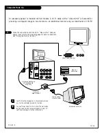
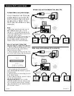
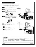
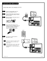
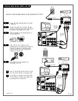
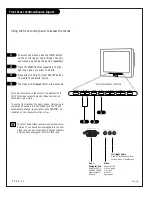
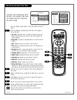
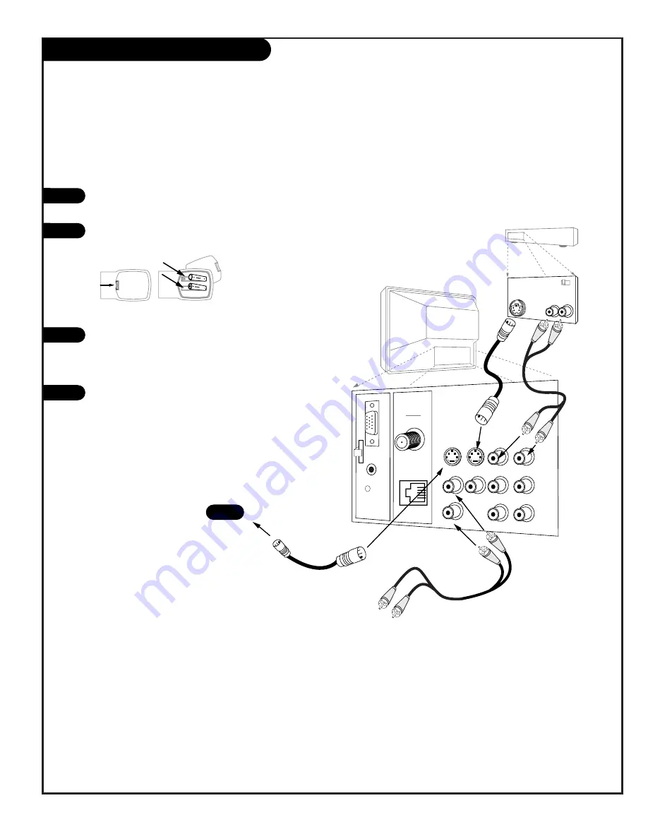
Your Gateway Destination II PC/TV may be connected to a Super-VHS VCR through the S-Video
Input located on the connection panel on your TV. Also, you may “daisy chain” up to four TVs to
one Super VHS VCR through the special S-Video LOOP OUT connection.
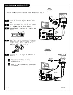
Hook up your S-VHS VCR to your Destination II
PC/TV according to the diagram below.
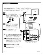
Remove the back of the remote and put in two
AAA batteries.
Plug in your TV. Do not plug it into a switched
outlet. Your TV is designed to operate on standard
current, 120-volt 60 Hertz AC. Do not attempt to
operate it on DC Current.
If you wish to “daisy chain” more than one TV to
receive the S-VHS signal, you will need to make
the following connections with an S-Video cable,
inserting one end of the cable into the LOOP OUT
port with the other end inserted into a S-Video In
port of your second TV or equivalent input for any
other brand of TV.
1
2
3
4
4
back of
remote
Hook Up an S-VHS VCR to your TV
Summary of Contents for C13A03D
Page 50: ...P A G E 5 1 206 3492 O...
Page 51: ...P A G E 5 2 206 3602...
Page 52: ...P A G E 5 3 206 3492 O...
Page 53: ...P A G E 5 4 206 3602...
Page 54: ...P A G E 5 5 206 3492 O...
Page 55: ...P A G E 5 6 206 3492 O...
Page 56: ...P A G E 5 7 206 3492 O...
Page 57: ...P A G E 5 8 206 3492 O...
Page 58: ...P A G E 5 9 206 3492 O...
Page 59: ...206 3643...

