


CM154
1-8
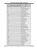
XC - MENUS
905-10525 USER MENUS
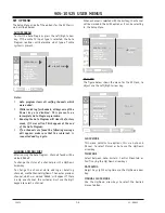
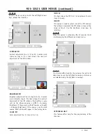
SET UP MENU
The Setup Menu and all of the options for the XC Chassis
are described below.
AUTO PROGRAM
To start the Auto Program, press the Left/Right arrow
key. If the cable TV input type is selected, the Auto
Program routines will determine what type of cable
system is present.
EZ PROGRAM
ADD/DEL/SURF
EZ CLOCK
CAPTIONS
CAPTION/TEXT
LANGUAGE
SOURCE/MENU
CABLE TV
AIR ANTENNA
B C
A
D
B C
A
D
MOVE
BACK
MENU
SET UP
SET UP
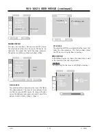
Notes:
•
Auto program clears all surfing channels which
were added.
•
While searching for channels, all keys except the
Power key are disabled. This prevents an
incomplete Auto Program procedure.
•
Running the Auto Program will clear the factory
mode, if it was active. This happens at the end
of the Auto Program.
•
If no channels are found the following message
will appear: make sure that the cable/ant. is
connected and try again.
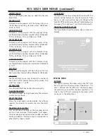
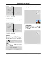
CHANNEL ADD/DEL/SURF
After running the Auto Program, channels found will be
marked ‘Added’.
To change the status of a channel press the Up/Down
Arrow key.
To change the channel while adding or deleting
channels, use the Channel Up/Down. The next or previous
channel, which was marked ‘Added’, will appear. If there
is only one channel, the customer must use the digit
keypad to select a channel.
When a channel is selected with the Surf key, the channel
will be marked in the SURF option or it can be selecting
in the Setup Menu.
EZ PROGRAM
EZ CLOCK
CAPTIONS
CAPTION/TEXT
LANGUAGE
SOURCE/MENU
ADD/DEL/SURF
B C
A
D
B C
A
D
DELETE
SURF
ADDED
CH 12
MOVE
BACK
MENU
SET UP
SET UP
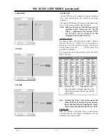
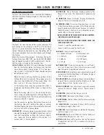
EZ CLOCK
The figure below shows the menu for the EZ Clock, to
adjust use the Left/Right arrow key.
EZ PROGRAM
ADD/DEL/SURF
CAPTIONS
CAPTION/TEXT
LANGUAGE
SOURCE/MENU
EZ CLOCK
B C
A
D
B C
A
D
TO SET
PRESS
SET UP
SET UP
MOVE
NEXT
MENU
NEXT MENU
CLOCK MODE
This menu contains two options, this are Auto and
Manual. To select Manual or Auto use the Up/Down
arrow key.
TIME ZONE
Select between Auto, Eastern, Central, Mountain or
Pacific using the Up/Down arrow keys.
DAY SAVING
Adjust Day Light Saving time use the Up/Down arrow
key.
MANUAL CLOCK MODE
Use the Up/Down arrow keys to select the desired
manual option.
USER MENUS 905-10525
Summary of Contents for C27A25
Page 6: ...TOC 2...
Page 22: ...1 16...
Page 26: ...2 4...
Page 42: ......
Page 43: ......
Page 44: ......


