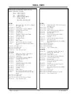
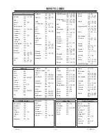
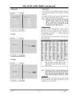
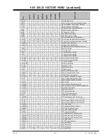
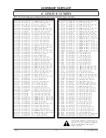
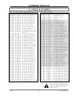
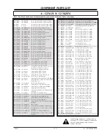
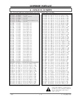
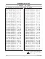
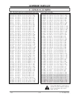
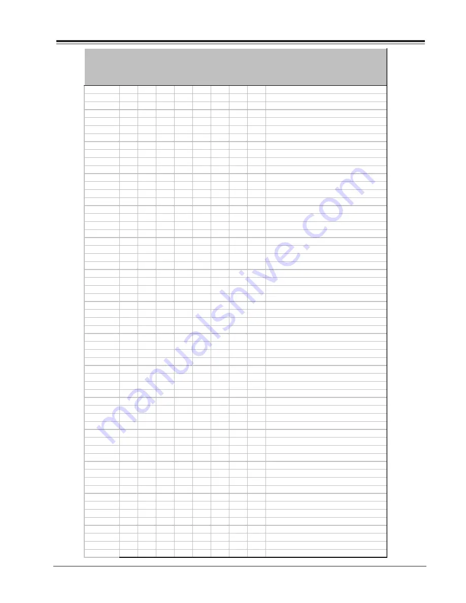
background image

CM154

2-3

XC - FACTORY MENU

905-10525 FACTORY MENU (continued)

Item

C

27A

25

C

27A

25T

6

C

32A

26

C

32A

26T

6

C

36A

26

C

36A

26-

8

C

36A

26T

6

C

36A

26T

6-

8

D

e

scri

p

ti

o

n

0  F  MODE

0

0

0

0

0

0

0

0

Factory mode pref.

1  PRE  PX

0

0

0

0

0

0

0

0

Used to store customer menu adjustment

2  V  POS

15

15

15

15

15

15

15

15

Moves captions and displays vertically

3  H  POS

9

9

9

9

9

9

9

9

Moves captions and displays

4  LEVEL

1

1

1

1

1

1

1

1

Selects Zenith or private IR codes

5  BAND

0

0

0

0

0

0

0

0

Broadcast band adjustment

6  AC  ON

0

0

0

0

0

0

0

0

AC Power Only Off/On

7  RF  BRT

29

29

36

36

29

29

29

29

Brightness for RF mode

8  AX  BRT

29

29

36

36

29

29

29

29

Brightness for Aux. mode

9 MAXCON

51

51

51

51

63

63

63

51

Sets customer control for contrast 

10 V.SIZE

66

66

100

100

175

100

175

100

Vertical amplitude adjustment variable

11 H.SIZE

150

150

100

100

184

100

184

100

Horizontal amplitude adjustment variable

12  VPHASE

0

0

3

3

0

0

0

0

Shifts picture vertically

13 HPHASE

18

18

18

18

18

18

18

18

Shifts picture horizontally

14  H  AFC

1

1

1

1

1

1

1

1

Horizontal automatic frequency control

15  RF  BPF

0

0

0

0

0

0

0

0

Band Pass Filter

16  3.58  T

1

1

1

1

1

1

1

1

3.58 MHz Trap

17  R  CUT

0

0

0

0

0

0

0

0

R channel cutoff control

18  G  CUT

0

0

0

0

0

0

0

0

G channel cutoff control

19  B  CUT

0

0

0

0

0

0

0

0

B channel cutoff control

20 G GAIN

90

90

90

90

90

90

90

90

B & W Tracking Adjustment

21 B GAIN

90

90

90

90

90

90

90

90

B & W Tracking Adjustment

22  60HZSW

2

2

2

2

2

2

2

2

60 Hertz Switched

23  WHCOMP

1

1

1

1

1

1

1

1

White compression 

24  6  KEYS

1

1

1

1

1

1

1

1

Keyboard  Types

25  F  JACK

0

1

1

1

1

1

1

1

Front Jack Enable

26  XTAL

0

0

0

0

0

0

0

0

External crystal

27 AUDLVL

46

46

42

42

42

42

42

42

Audio Level for Main Tuner

28 AUDLV2

46

46

42

42

42

42

42

42

Audio Level for Second Tuner

29  RF  AGC

50

50

50

50

50

50

50

50

Weak channel adjustment

30 PIFVCO

70

70

70

70

70

70

70

70

PIF Voltage Controlled Oscillator 

31  A  ATT

9

9

9

9

9

9

9

9

Audio Attenuator for Main Tuner

32  A  VCO

31

31

31

31

31

31

31

31

Audio Voltage Control Oscillator

33 A FLTR

31

31

31

31

31

31

31

31

Audio Filter

34 SPCTRL

31

31

31

31

31

31

31

31

Adjustment of stereo separation

35 W BAND

31

31

31

31

31

31

31

31

Audio Wide Band Low Frequency separation 

36  SELDEL

15

15

15

15

15

15

15

15

Delay of output signal

37  VHYPLEV

14

11

14

11

14

14

11

11

Auto Gain Control

38  YOFFST

0

0

0

0

0

0

0

0

PIP Luminance Offset

39  PLLITC

2

2

2

2

2

2

2

2

PIP PLL Synchronization

40  HFP

0

0

0

0

0

0

0

0

Horizontal Fine Position

41 PINCRA

15

5

15

5

15

15

5

5

PIP Regenerated Color Carrier Freq.

42  PR  CUT

0

0

0

0

0

0

0

0

Adjustment of Blanking level of R DAC

43  PG  CUT

0

0

0

0

0

0

0

0

Adjustment of Blanking level of G DAC

44  PB  CUT

0

0

0

0

0

0

0

0

Adjustment of Blanking level of B DAC

45 CFRAME

16

0

16

0

16

16

0

0

PIP Color Frame

46  FRWIDH

2

2

2

2

2

2

2

2

PIP Horizontal Width of Frame

47  FRWIDV

1

1

1

1

1

1

1

1

PIP Vertical Width of Frame

48  CKILL

2

2

2

2

2

2

2

2

PIP Color Killer Threshold

49  YPEAK

4

7

4

7

4

4

7

7

PIP Luminance Peaking

50 PRGAIN

205

225

190

225

190

190

225

225

PIP Amplitude of R Output Signal

51 PGGAIN

205

225

190

225

190

190

225

225

PIP Amplitude of G Output Signal

52 PBGAIN

205

225

190

225

190

190

225

225

PIP Amplitude of B Output Signal

53  PCOLON

0

0

0

0

0

0

0

0

PIP Color Killer 

54  PFRSEL

0

0

0

0

0

0

0

0

3D PIP Frame Selection

55 PIP X1

17

36

17

36

16

14

36

36

PIP position X1

56 PIP Y1

12

22

9

21

9

9

21

21

PIP position Y1

57 PIP X2

109

211

109

211

110

108

211

211

PIP position X2

58 PIP Y2

73

146

72

144

74

73

144

144

PIP position Y2

Summary of Contents for C27A25

Page 1: ...2 Servicing Troublshooting 3 Model Part Lists 4 Exploded Views 5 Schematics PCB Layouts 6 Published by Technical Publications Zenith Electronics Corporation 201 James Record Road Huntsville Alabama 3...

Page 2: ...d 150V AC type capacitor between a known good earth ground water pipe conduit etc and the exposed metallic parts one at a time Measure the AC voltage across the combination of 1500 ohm resistor and 15...

Page 3: ...lter CX3000 RX3002 and finally to pin 29 through RX3000M The Zener Diode s function is to keep a constant voltage on its terminals Since the Zener is in series with the ICX2200 see the figure below an...

Page 4: ...ng up the external power supply from 0 to 8 volts until the circuit shutsdown SAFETY CIRCUIT TEST PROCEDURE Equipment required a K V DC meter 0 to 30 KV high Z b Video Generator Before turning the TV...

Page 5: ...OR 3 2 AGC DELAY 3 2 MTS STEREO DECODER ALIGNMENT 3 2 STEREO LEVEL ADJUSTMENT 3 2 PURITY CONVERGENCE SETUP PROCEDURE 3 3 PRELIMINARY SETUP 3 3 PURITY ADJUSTMENT 3 3 CONVERGENCE ADJUSTMENT 3 3 VERTICAL...

Page 6: ...TOC 2...

Page 7: ...C B C E ICX3802 FX3602 2C5 R OUT A 19268 FRONT JACK YC VIDEO RIGHT LEFT ON OFF VOL DWN VOL UP CH DWN CH UP MENU SW1 SW4 SW2 SW5 SW6 SW3 6K2 IR1 O UT VCC G ND 5F2 5C2 1 IC5100 CRT G OUT B OUT GND V1 GN...

Page 8: ...s closed caption menu TV VCR SOURCE Steps through source options SURF Turns Surf Channel On Off CHANNEL Up Down Selects next channel in TV s memory Press and hold to repeat NUMBER PAD Selects channels...

Page 9: ...Steps through source options SURF Turns Surf Channel On Off CHANNEL Up Down Selects next channel in TV s memory Press and hold to repeat NUMBER PAD Selects channels directly MENU Displays menus for TV...

Page 10: ...ER Auto Find has tried all of the codes If the product you want to control has not turned off this remote will not work with that product To cancel Auto Find press PRG at any time during Auto Find CAB...

Page 11: ...3 117 119 127 128 139 Tatung 106 Teknika 103 112 121 124 139 Telerent 103 121 Toshiba 110 111 134 171 XR1000 121 154 Yorx 119 Zenith 101 121 142 149 152 177 Zenith Star Sight 175 Audio CD ADC 940 ADO...

Page 12: ...227 228 240 242 244 249 260 266 282 283 284 285 286 287 288 708 710 711 725 Realistic 206 208 212 213 214 231 265 730 Saisho 722 Salora 297 Samsung 220 230 238 Sansui 239 289 292 709 726 Sanyo 206 21...

Page 13: ...320 Paragon 333 Philips 325 327 347 350 352 354 355 521 Pioneer 315 343 PrimeStar 388 513 ProScan 510 517 Radio Shack 362 RCA 510 517 RCA DSS 341 373 394 Realistic 506 Regal 366 Regency 329 Samsung 32...

Page 14: ...tatus of a channel press the Up Down Arrow key To change the channel while adding or deleting channels use the Channel Up Down The next or previous channel which was marked Added will appear If there...

Page 15: ...CAPTIONS This feature allows the customer to select Off On or Ez Muted options To change the status of captions press the Up Down arrow key to select either Off On or Ez Mute EZ PROGRAM ADD DEL SURF E...

Page 16: ...ection of Main determines the signal that feeds the video processor This menu has two options these are Main Source and PIP Source To change of option to use the Up Down arrow keys and selects one of...

Page 17: ...eo and SAP If SAP is selected but the particular channel does not support SAP the channel actual will be reproduced Note If the program does not support Stereo there the audio will output in mono SOUN...

Page 18: ...to allow Password entry TO ENTER PASSWORD The software accepts four digit codes only The customer must enter a password REPEAT PASSWORD After a four digit code has been entered the software requires...

Page 19: ...mer to select a channel label for the current station This channel label is displayed in the Channel Time display Initially all channel labels are set to _ _ _ _ which means that auto label is selecte...

Page 20: ...ss if the source is on the RF source or AuxBrt Customer Brightness if the source is on the AUX source RfBrt and AuxBrt appear in the factory menu COLOR PIP Color adjustment has 15 steps 0 to 15 TINT P...

Page 21: ...DD OR DELETE A CHANNEL ADD DEL SURF DELETE SURF ADDED SLEEP TIMER The user can choose to activate the timer to turn off the Television in 10 20 or 30 minutes or 1 1 30 2 3 or 4 hours just by clicking...

Page 22: ...1 16...

Page 23: ...EAROM Selections are Cus tom and Preset Store Settings for Contrast Bright ness Color and Tint are stored in this manner 0 is custom and 1 is Preset stored 02 VERT P0S Moves On Screen Displays vertic...

Page 24: ...AUDIO SPECTRL Adjustment of stereo separation 3kHz Range is 0 63 35 WIDE BAND Adjustment of stereo separation 300kHz Range is 0 63 36 DELAY PIP SELECT Delay of output signal Range is 0 15 Typical is 1...

Page 25: ...42 42 42 42 Audio Level for Main Tuner 28 AUDLV2 46 46 42 42 42 42 42 42 Audio Level for Second Tuner 29 RF AGC 50 50 50 50 50 50 50 50 Weak channel adjustment 30 PIFVCO 70 70 70 70 70 70 70 70 PIF V...

Page 26: ...2 4...

Page 27: ...available on an exchange basis for the 32 and 36 models If the CRT or Video processor IC are replaced Black White tracking must be reset Refer to the FACTORY MENU section of this book for Black White...

Page 28: ...lor level control to normal IF AND AUDIO SERVICING VIDEO DETECTOR If there is no viewable picture on screen access the Factory Menu and check default settings for the following items 35 RF AGC should...

Page 29: ...s separately to converge the red and blue lines horizontally Move the two tabs together around the neck of the CRT in a 45 arc from the top dead center position to converge the red and blue lines vert...

Page 30: ...y against the CRT glass The CRT glass surface should be clean and free of dust and other foreign material UNUSUAL TILT CASE There may be some instances where the picture tube and yoke will require ver...

Page 31: ...IR 994 10025 Wedge Rubber A 18681 01 Line Cord Assy with Yeonho Connector A 19112 CRT Assembly w Deflection Yoke and Beam Bender P014 12351 05 Cabinet Front P014 12352 03 Cabinet Rear P046 10594 02 K...

Page 32: ...r P046 10594 02 Knob Array Push Button 6 Position PA 19392 03 Cover Jack Panel Front C36A26T6 809 10558 Module Main 36V with 2 PIP 6 Jacks Keyboard MTS Digital Comb Inv 020 04330 34 Coil Degausser 049...

Page 33: ...information is for models in and out of warranty The 27 XC models are com ponent level repair To Order Parts call 1 888 3 ZENITH fax 1 888 6 ZENITH By Mail ZENITH NATIONAL PARTS SALES AND DISTRIBUTIO...

Page 34: ...o AB C1234M 022 08370 24A Cap 22 000 pfd 10 16V Ceramic Chip AB C1401M 022 08370 22A Cap 15 000 pfd 10 16V Ceramic Chip AB C1402M 022 08366 18A Cap 6 800 pfd 10 50V Ceramic Chip AB C1403M 022 08370 22...

Page 35: ...511M 022 08352 22A Cap 27 pfd 5 50V Ceramic Chip AB C2512M 022 08352 22A Cap 27 pfd 5 50V Ceramic Chip AB C2517M 022 08376 32A Cap 100 000 pfd 80 20 16V Chip AB C2518M 022 08376 32A Cap 100 000 pfd 80...

Page 36: ...Ceramic Chip AB C6061M 022 08352 28A Cap 47 pfd 5 50V Ceramic Chip AB C6062M 022 08352 28A Cap 47 pfd 5 50V Ceramic Chip AB C6064 022 08312 07A Cap 4 7 mfd 20 50V Electro AB C6065M 022 08368 20A Cap...

Page 37: ...age Regulator AB ICX3701 162 00028 01 Opto Coupler AB ICX3702 221 00265 03A Integrated Ckt Adjustable Shunt Regulator AB ICX3801 221 00213 09 Integrated Ckt 9 Volt 1 Amp Linear Regulator AB ICX3801 P1...

Page 38: ...sistor Chip 100 Ohm 5 1 10W AB R1207M 063 11059 09A Resistor Chip 22 Ohm 5 1 10W AB R1208M 063 11059 13A Resistor Chip 33 Ohm 5 1 10W AB R1209M 063 11059 25A Resistor Chip 100 Ohm 5 1 10W AB R1210M 06...

Page 39: ...1 10W AB R2408M 063 11059 17A Resistor Chip 47 Ohm 5 1 10W AB R2409M 063 11059 55A Resistor Chip 1 8K Ohm 5 1 10W AB R2410M 063 11059 81A Resistor Chip 22K Ohm 5 1 10W AB R2411M 063 11059 61A Resistor...

Page 40: ...53 Wire Solid Bare 22 Ga Copper AB R5130M 063 11059 85A Resistor Chip 33K Ohm 5 1 10W AB R6001M 063 11059 65A Resistor Chip 4 7K Ohm 5 1 10W AB R6002M 063 11059 33A Resistor Chip 220 Ohm 5 1 10W AB R6...

Page 41: ...X3702 063 10235 72 Resistor Film 1K Ohm 5 1 4W AB RX3703 063 10236 38 Resistor Film 560K Ohm 5 1 4W AB RX3704 063 11285 07 Resistor Film 174K Ohm 0 1 1 4W AB RX3705 063 11283 45 Resistor Film 3 57K Oh...

Page 42: ......

Page 43: ......

Page 44: ......

Page 45: ...5 809 10051 8 REMOTE CONTROL 124 00233 05 124 00233 05 PRG POWER VCR CABLE SURF FLASHBK MUTE TV AUX CHANNEL CHANNEL VOLUME 3 2 1 4 5 6 7 8 9 0 ENTER CLOCK MENU VCR PIP ONCE PIPCh WEEKLY DAILY REVIEW C...

Page 46: ...9 02214 8 REMOTE CONTROL 124 00233 06 124 00233 06 PRG POWER VCR CABLE SURF FLASHBK MUTE TV AUX CHANNEL CHANNEL VOLUME 3 2 1 4 5 6 7 8 9 0 ENTER CLOCK MENU VCR PIP ONCE PIPCh WEEKLY DAILY REVIEW CC FR...

Page 47: ...6 01 P014 12356 01 P014 12356 01 7 MAIN MODULE 009 2170 009 2170 01 809 10558 809 10559 8 REMOTE CONTROL 124 00233 06 124 00233 06 124 00233 06 124 00233 06 PRG POWER VCR CABLE SURF FLASHBK MUTE TV AU...

Page 48: ...SECTION 6 Interconnect Diagram VC1 1CV 1 IC5100 CRT 1 1 2K6 1 1 E B C B C E 1 ICX3802 FX3602 2C5 R OUT G OUT B OUT GND R OUT G OUT B OUT GND FRONT JACK YC VIDEO RIGHT LEFT 215 V FIL V GND 215 V GND 2...

Page 49: ...K VDC VSB 15 56uH E B C E B C 2200pF 2KV VSB 18 F 43283 PROV 3 57K TUNE 5V VSW 18 4 3 2 1 PROV 162 51 SB 5V P L 250V VSB 15 560K VSB 15 0 68 5W B 1 2W 1 5K 3 1 2 680 P L VDR 0 12 3W P L PROV 50V 150K...

Page 50: ...0uF 50V 10 LOW LEAKAGE 100 3 3uF 50V 10 LOW LEAKAGE 10uF 25V 4 7uF 50V 50V 5600pF 3K 3 3K 10uF 25V 100uF 16V 10uF 25V 25V 0 01uF 2 2K 470uF 25V SHT 4 PWR MUTE 4 7uF 50V ABL 15 10uF 50V 1 61 9K 4 7uF 5...

Page 51: ...50V PROV 0 0 330 0 01 25V 1uH 2 2K 47K 27 28 29 30 31 32 33 34 35 36 37 38 26 25 24 23 22 21 20 19 18 17 16 15 39 40 41 42 43 44 45 46 47 48 49 50 51 52 14 13 12 11 10 9 8 7 6 5 4 3 2 1 M37273 126 334...

Page 52: ...0V 470PF 4277 09A 0 82uH 100 3 58MHZ 224 27A 10uH 12UH 47 15uH 16V 100uF 25V 0 01uF 4 7uF 50V 47 120 50V 120pF 16V 100uF 50V 10uF E 0 PROV 50V 220pF 50V 27pF 224 178 503KHZ 29 30 31 32 33 34 35 36 37...

Page 53: ...1 1264 01A 25V 1K 0 1 50V 180K SBF 5V 1 2W 560 F 1 SHT 4 HORZ SIZE 100uF 35V 215V 10uF 50V F 1 SHT 4 VERT SIZE 0 012 630V P L PROV 0 47K 121 1264 01 4 7K 15K 1 2W 2 7 4 7uF 50V 15K 2KV P L F PROV F 43...

Page 54: ...18uH SWF 9V 75 16V 47uF 1K 50V 10uF 50V 10uF 33V 50V 12pF 50V 4 7uF 50V 1uF 50V 10uF PROV F 12 SHT 5 TV IN E 12 SHT 5 C OUT D 12 SHT 5 VIDEO SYNC D 12 SHT 5 Y OUT 50V 1uF SHT 4 B 1 Y MICRO 50V 1uF 50...

Page 55: ...7uH 1 P L 1 2W 1K 215 VSW 45 1 2W 1K 1 2W 1K 1 2W 1K 100K 1 2W 2 2 2 4 0 01 2KV 1 8K 50V 12pF 2 4 43 1 50V 12pF P L 15K 910 50V 12pF PROV 10K 1 220K 1 2W 910 2 4 1 100K 1 2W 910 2 100K 1 2W 2 2 1 250...

Page 56: ...10uF PROV 1 5K 6 2K SWA 9V 50V 18pF SWF 9V 33pF 18uH 47K 56pF 2 2K 33uF 56K 3 3K 22K 01uF 50V 50V 10uF 27pF 50V 12pF 27pF SWF 9V 1K 1K 100 22K 1 5K 3 3K 50V 10uF 4 7K 120pF AVDD YOUT BIAS2 COUT BIAS3...

Page 57: ...5V PROV 50V 2 2uF 820 50V 2 2uF 50V 0 1 50V 0 1 G 12 SHT 4 FASTBLANK 1K 1K 50V 62pF G 12 SHT 4 G UP G 12 SHT 4 B UP 0 1 50V G 12 SHT 4 R UP 0 1 50V SHT 7_A 12 SHT 9_C 12 SHT 5_A 1 SHT 4_C 12 SCL SHT...

Page 58: ...202 C2101 C2103 C2104 C2108 C2251 C842 DX3501 ICX2100 11 1 CX3203 CX3302 C3207 CX2111 C1415 RX3207 R2117 R2113 R2228 R6055 R6054 RX3208 E C B QX3202 CX3217 LX3201 CX3209 W3200 C B E QX3301 W3202 W3201...

Page 59: ...C B E C B E C B 11 10 2 1 E C B 1 E C B 1 1 1 OUT G IN 10 1 1 28 15 14 1 36 48 25 13 24 1 36 48 25 13 24 1 E B C E B C E B C E B C 29 28 42 14 56 1 1 C E B 52 40 27 26 13 1 8 5 4 1 1 VCC OUT 15 9 8 1...

Reviews: