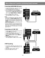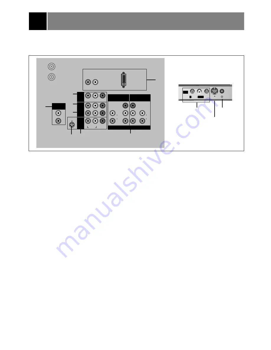
External Equipment Connection and Viewing Setup
29
1. IN 1 JACKS : Connect external equipment outputs (VCR, LASER DISC, CAMCORDER) to these
inputs. Use the tv/video button to select
Video 1
.
2. IN 2 JACKS : Connect external equipment outputs (VCR, LASER DISC, CAMCORDER) to these
inputs. Use the tv/video button to select
Video 2
.
3. IN 3 JACKS : Connect external equipment outputs (VCR, LASER DISC, CAMCORDER) to these
inputs. Use the tv/video button to select
Video 3
.
4. IN 4 JACKS : Connect external equipment outputs (VCR, LASER DISC, CAMCORDER) to these
inputs. Use the tv/video button to select
Video 4
.
5. DVD/DTV INPUT JACKS : Connect component output jacks to these inputs. Use the tv/video or
comp/dvi button to select
Component
1
,
Component
2
.
6. OUT JACKS: Connect external equipment inputs (VCR, Audio amplifier) to these outputs for recording
or monitoring the selected program.
7. DVI INPUT JACKS: Connect set-top box to these inputs. Use the tv/video or comp/dvi button to
select
DVI
.
8. VARIABLE AUDIO OUT JACKS: Connect analog stereo amplifier to your front speaker.
9. EARPHONE JACK
Note: This TV is programmed to remember which mode it was last set to, even if you turn the TV off.
ANTENNA 1
ANTENNA 2
VIDEO
R-AUDIO-L
L
R
AUDIO
Y
P
R
P
B
Y
P
R
P
B
DVD/DTV INPUT
COMPONENT1
480i/480p/720p/1080i
COMPONENT2
480i/480p/720p/1080i
VIDEO
S-VIDEO
R
L/MONO
R
L
DVI AUDIO INPUT
DVI INPUT
(DIRECTV STB)
OUT
IN3
IN2
IN1
VARIABLE
AUDIO OUT
L
AUDIO
R
L
AUDIO
R
75
Ω
L
L
75
Ω
L
L
7
2
3
6
8
S-VIDEO
INPUT JACK
S-VIDEO
INPUT JACK
You can connect additional equipment, such as VCRs, camcorders etc. to your TV.
Connection panels shown here may be somewhat different from your TV.
Here is an example drawing of a typical jackpack layout.
in4
video
S-video
audio
L/mono
R
1
5
4
9

