


- 14 -
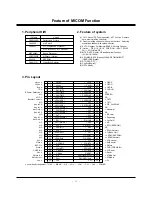
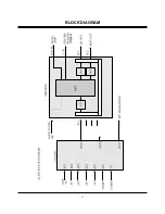
Feature of MICOM Function
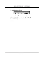
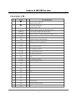
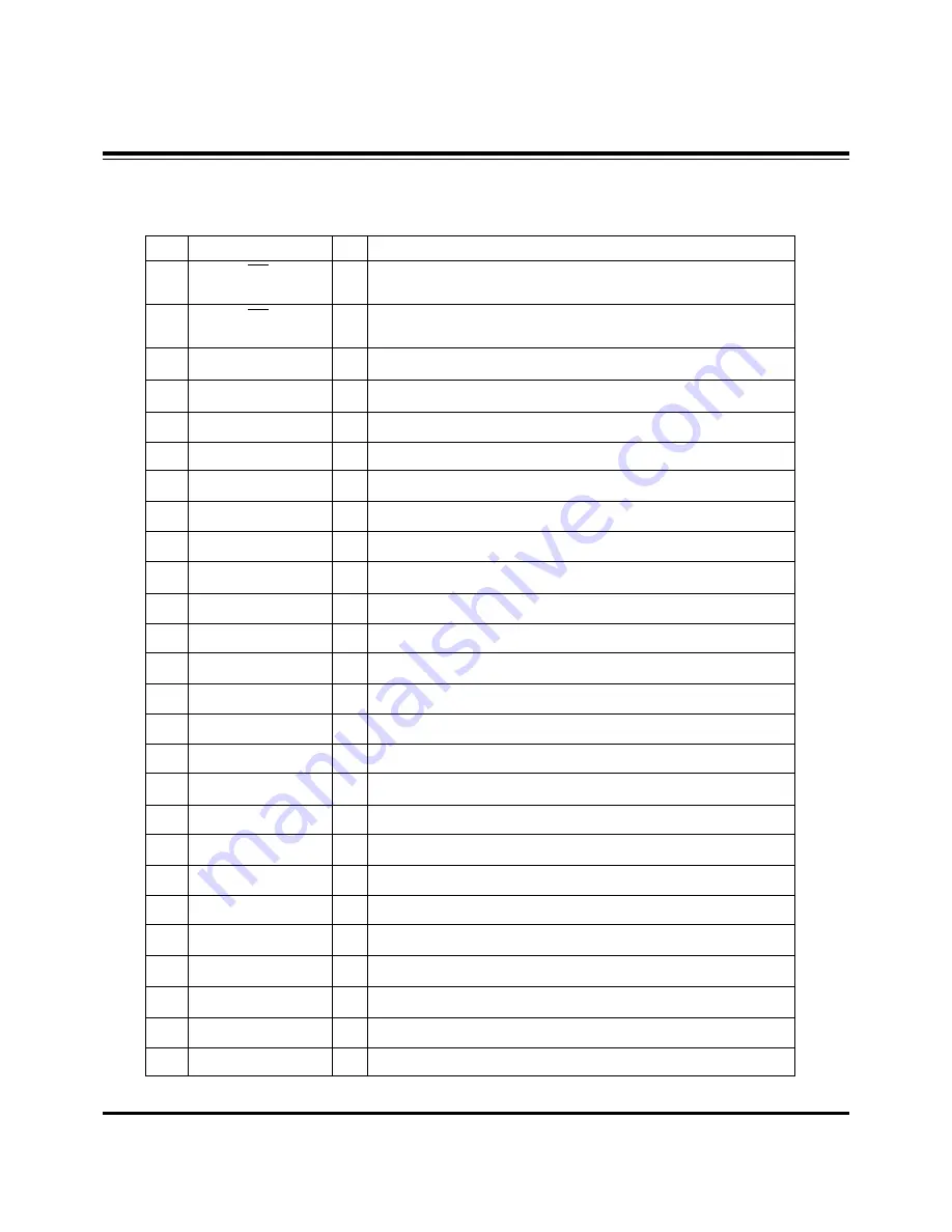
4. Description of PIN
No.
Symbol
Functional Description
1
2
3
4
5
6
7
8
9
10
11
12
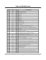
13
14
15
16
17
18
19
20
21
22
23
24
25
26
HD
VD
Eye in
IR(Remocon)
B_ICVoltage
N.C
AGC
Booster Control
N.C
Key-In2
Key-In1
Key_Out0
Key_In0
N.C
Key-In3
Key_Out1
N.C
N.C
N.C
N.C
N.C
N.C
N.C
AVcc
Filter
RVCO
¤ˇ
¤ˇ
¤ˇ
¤ˇ
¤
¤
¤
¤
¤
¤
¤ˇ
¤
¤
O
Horizontal Sync. Signal Input
O
Input Polarity : Active “L“
O
Vertical Sync. Signal Input
O
Input Polarity : Active “L“
O
Inputs C Data of Chroma picture (Data is input by A/D)
O
For remote control input(uses external interupt)
O
Detects Power of IC(outputs initial data after resetting IC in Low)
O
Inputs the century of input image signal
O
Booster of Main Tuner On/Off output
O
Local Key Input Terminal
O
Local Key Input Terminal
O
Local Key Output Terminal
O
Local Key Input Terminal
N.C
O
Local Key Input Terminal
O
Local Key Output Terminal
N.C
N.C
O
Analog Power
O
Filter Terminal for CAPTION
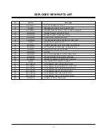
Summary of Contents for C30W46
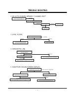
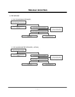
Page 17: ...17 TROUBLE SHOOTING...
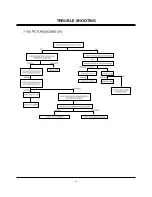
Page 18: ...18 TROUBLE SHOOTING...
Page 19: ...19 TROUBLE SHOOTING...
Page 20: ...20 TROUBLE SHOOTING...
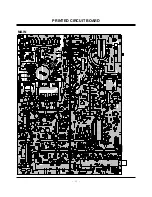
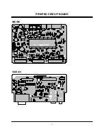
Page 21: ...21 PRINTED CIRCUIT BOARD MAIN...
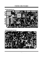
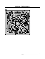
Page 22: ...22 PRINTED CIRCUIT BOARD PROGRESSIVE TOP PROGRESSIVE BOTTOM...
Page 23: ...23 MICOM PRINTED CIRCUIT BOARD SIDE A V...
Page 24: ...24 CPT PRINTED CIRCUIT BOARD...
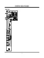
Page 25: ...25 CONTROL PRINTED CIRCUIT BOARD...
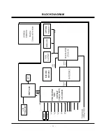
Page 27: ...27 Option BLOCK DIAGRAM...
Page 38: ......
Page 39: ......
Page 40: ......


