X-RADIATION
To prevent possible exposure to radiation caused by excessive CRT Anode
voltage, the High Voltage Shutdown circuit senses the level of flyback pulse
from “Flyback Transformer” representative of the actual high voltage on the
CRT anode. When this level exceeds a predetermined voltage, the circuit shuts
down the horizontal drive, preventing further generation of anode voltage. In
this condition, the horizontal drive is “latched” off. The drive will remain off until
power (via remote control or front panel) is cycled from “Off” to “On”.
CRT ANODE HIGH VOLTAGE MEASUREMENT PROCEDURE
Each screen size has its own safe operating Anode Voltage and shutdown
voltage. Critical Safety components (designated with an “X” in the component
designator) are designed to operate the CRT at a safe operating Anode voltage
and provide proper shutdown thresholds. If replacement of any of these
components are deemed necessary, it is important to use original type Zenith
replacement components.
After replacement is made, confirm proper Anode voltage using the following
procedure.
Measurement of the CRT Anode voltage must be performed using a high
impedance high voltage meter, with no visible raster on the screen, and
operating at nominal horizontal scanning frequency.
Connect a strong broadcast signal (or TV signal generator operating at
15.734kHz horizontal scanning rate) to the RF input.
After the CRT is discharged, connect a high impedance high voltage meter at
the distribution block. Turn the television “on” and confirm a good signal is
being displayed . Reduce Brightness and Contrast settings until the picture is
well extinguished.
Observe the Anode voltage meter reading and compare with the table below
for the proper CRT screen size. If the voltage reading is higher that the
maximum, verify circuit component values and proper operation.
EQUIPMENT REQUIRED
a) Video Generator.
b) HV DC meter (0 to 40 KV, high Z).
c) External variable power supply (0V to 7.5VDC @ 5Amps minimum).
TEST PROCEDURE
To verify the Shutdown Circuit is operating properly proceed with the following
procedure:
7.5V DC between R446 and R448 on the High Voltage Deflection
PCB. If there is no raster and set goes into Shutdown, then the Shutdown
Circuit is functional. If the set doesn’t go into Shutdown, then the Circuit is
defective.
TIPS ON PROPER INSTALLATION
1. Never install any receiver in a closed-in recess, cubbyhole, or closely fitting
shelf space over, or close to, a heat duct, or in the path of heated air flow.
2. Avoid conditions of high humidity such as: outdoor patio installations where
dew is a factor, near steam radiators where steam leakage is a factor, etc.
3. Avoid placement where draperies may obstruct venting. The customer
should also avoid the use of decorative scarves or other coverings that
might obstruct ventilation.
4. Wall-and shelf-mounted installations using a commercial mounting kit must
follow the factory-approved mounting instructions. A product mounted to a
shelf or platform must retain its original feet(or the equivalent thickness in
spacers) to provide adequate air flow across the bottom. Bolts or screws
used for fasteners must not touch any parts or wiring. Perform leakage tests
on customized installations.
5. Caution customers against mounting a product on a sloping shelf or in a
tilted position, unless the receiver is properly secured.
6. A product on a roll-about cart should be stable in its mounting to the cart.
Caution the customer on the hazards or trying to roll a cart with small
casters across thresholds or deep pile carpets.
7. Caution customers against using a cart or stand that has not been listed by
Underwriters Laboratories, Inc. for use with its specific model of television
receiver or generically approved for use with TVs9 of the same or larger
screen size.
8. Caution customers against using extension cords. Explain that a forest of
extensions, sprouting from a single outlet, can lead to disastrous
consequences to home and family.
- 3 -
SERVICING GUIDELINES FOR X-RADIATION PROTECTION
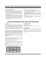
SCREEN
SIZE
27
32
128.5±2%
30
31.5
B+ VDC
(0 BEAM)
COMPONENT LEVEL REPAIR
HV NOM
KV
HV MAX
KV
PRODUCT SAFETY SERVICING GUIDELINES FOR AUDIO-VIDEO PRODUCTS
Summary of Contents for C30W46
Page 17: ...17 TROUBLE SHOOTING...
Page 18: ...18 TROUBLE SHOOTING...
Page 19: ...19 TROUBLE SHOOTING...
Page 20: ...20 TROUBLE SHOOTING...
Page 21: ...21 PRINTED CIRCUIT BOARD MAIN...
Page 22: ...22 PRINTED CIRCUIT BOARD PROGRESSIVE TOP PROGRESSIVE BOTTOM...
Page 23: ...23 MICOM PRINTED CIRCUIT BOARD SIDE A V...
Page 24: ...24 CPT PRINTED CIRCUIT BOARD...
Page 25: ...25 CONTROL PRINTED CIRCUIT BOARD...
Page 27: ...27 Option BLOCK DIAGRAM...
Page 38: ......
Page 39: ......
Page 40: ......


