3-3
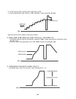
* To set final settings, fit best display guality while viewing screen.
• or, after inputting 5STEP signal, adjust as CONT adjusting as shown below.(COLER MAX)
• adjust best results while viewing oscilloscope and Screen.
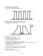
5) GAM0, GAM1 (GAM0: Black side, GAM1: White side) - Fixed(VR810, 811)
* Input RAMP signal and view TP(G) waveform, deside that GAM0 is black side knee point and GAM1 iswhite-
side knee point.
• GAM0 and GAM1 adjusting performs with CONT(VR803), because the amplitude linked.
6) CONT(VR803); White LEVEL Variable (2.8±0.1V)
Input RAMP signal, View TP(G) wareform, adjust amplitude to 3.2 ~ 3.5.
(VR803) (2.9V)
3.4
3.2
3.1
2.7
1.5
1
2.1
0.6
GND
BRIGHT
Black
(VR808)(2V)
Summary of Contents for DVP7771
Page 8: ...2 3 Deck Mechanism Section 430 430 001 430 002 002 006 005 004 003 002 431 431 007...
Page 32: ...MEMO...
Page 37: ...3 15 3 16 LCD P C BOARD LOCATION GUIDE LOCATION GUIDE...
Page 38: ...MEMO MEMO...
Page 44: ...3 42 3 43 6 PANTER CIRCUIT DIAGRAM waveforms page 3 58 3 59 2002 02 01 R14113A...
Page 45: ...3 44 3 45 7 MEMORY CIRCUIT DIAGRAM 2002 02 01 R14114A...
Page 47: ...3 48 3 49 9 CPLD CIRCUIT DIAGRAM 2002 02 01 R14116A...
Page 54: ...3 62 3 63 PRINTED CIRCUIT DIAGRAMS 1 MAIN P C BOARD LOCATION GUIDE LOCATION GUIDE...
Page 55: ...3 64 3 65 2 FRONT KEY P C BOARD LOCATION GUIDE LOCATION GUIDE...
Page 56: ...MEMO MEMO...


