Page 4 of 8
Filter Tap - Installation & Operating Instructions - 801085NZ - January 2013 v1.00
#
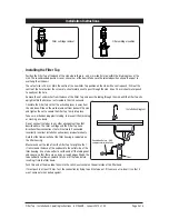
Installation Instructions
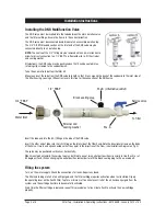
Pos.B
( Alternative outlet )
Pos. A
3/4” FBSP
1/2” FBSP
Strainer and
sealing washer
Service valve
Water Inlet
To filter
Black sealing plug
Installing the DNR Multifunction Valve
The DNR valve must be inserted into the tube between the main isolation valve
and the filter cartridge. Ensure the flow is in the correct direction.
The DNR valve must be connected downstream of an accessible isolation tap.
The 3/4”F- BSP threaded section on the inlet end of the DNR valve may be
connected directly to an isolation tap.
NOTE:
The centre of the 3/4” fitting may be removed with an 8mm allen key to
allow for direct connection to a 1/2” BSP Tap. Remember to re-fit the strainer
and sealing washer.
Alternatively, the DNR valve may be positioned so that it can be seated into a
retaining clip screwed to the cupboard wall.
Take the one metre tube from the filter kit.
Meaure and cut the tube from the DNR valve to length so that it runs around the back of the cupboard to the inlet side of
the filter housing. Leaving a little extra slack in this line for the connection of the DNR valve.
Insert the tube end into the (JG) fitting on the side of the DNR valve.
Insert the other end of tube into the (JG) fitting on the Inlet side of the filter head. Note the directional arrows on the body
of the Valve. It must end up connected so that they point in the direction of the Flow. (see Installation Diagram on Pg 3.)
The valve may be positioned vertically or horizontally.
When mounted horizontally the service tap may be fitted to one of two outlet port positions i.e axially in line (Pos A) or at
90 degrees (Pos B). When changing the outlet position remember to refit the black sealing plug to the un-used port.
Filling the system
Turn ‘on’ the water supply. Check the connections for leaks. Repair any found.
The filter and tubing are full of air until purged, and the filter cartridge requires activation when first installed. Flip up
the operating lever on the Zenith Filter Tap for a minimum of five minutes until all of the air has been purged from the
system, and the cartridge has time to become fully activated.
Every time the filter cartridge is replaced, repeat this procedure of a five minute flush to activate the new cartridge
properly.


