X-Radiation
To prevent possible exposure to x-radiation caused by excessive CRT
anode voltage, the CL chassis incorporate a “High Voltage Shut-
down” circuit. This circuit senses the level of a flyback pulse from the
“Flyback Transformer” representative of the actual high voltage on
the CRT anode. When this level exceeds a predetermined voltage, the
circuit shuts down the TV set, preventing further generation of anode
voltage.
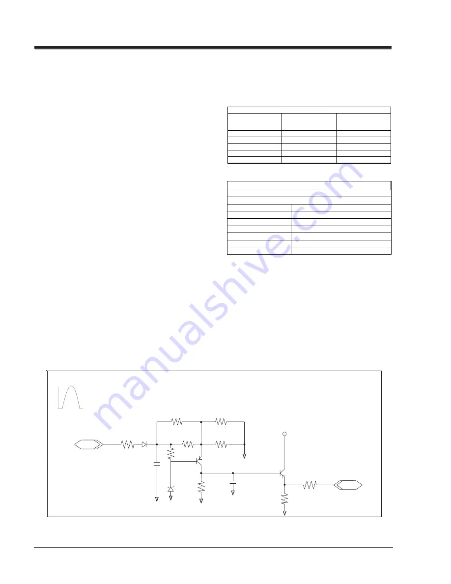
Shutdown Circuit Operation
(Refer to Figure below)
The flyback pulse voltage from pin 6 of TX3204 (Flyback Transformer)
is peak detected (rectified) by the action of diode DX3006 and ca-
pacitor CX3003. This forms a DC voltage appearing on CX3003 repre-
sentative of the CRT anode voltage (HV) produced by TX3204. This
voltage is divided down by precision resistors RX3013, RX3015,
RX3016 and RX3022. This lower voltage appears on the zener diode
ZDX3004; when this voltage exceeds by 3.5 Vdc the “zener voltage”
the HV shutdown occurs (pin 29 of ICX2200).
CRT Anode High Voltage Measurement Procedure
Each CRT screen size has its own safe operating anode and shut-
down voltage. Critical safety component (designated with an ‘X’ in
the component designator) are designed to operate the CRT at a
safe operating anode voltage and provide proper shutdown thresh-
olds. If replacement of any of these components are deemed
necessary, it is important to use original type Zenith compo-
nents. After replacement is made, confirm proper anode voltage
using the following procedure.
Measurement of the CRT anode voltage must be performed using a
high impedance-high voltage meter, with no raster on the screen,
and operating at nominal horizontal frequency, 15.75 Khz (NTSC
signal).
After discharging the CRT, connect a high impedance-high voltage
meter to the CRT anode. Turn the television ‘on’ and confirm a good
signal is being displayed. Reduce Brightness and Contrast settings
until the picture is well extinguished.
PRODUCT SAFETY SERVICING GUIDELINES FOR AUDIO-VIDEO PRODUCTS
ii
Observe the anode voltage meter reading and compare with the
table below for the proper CRT screen size. If the voltage reading is
higher than the maximum, verify circuit component values and
proper operation.
CRT Screen Size
Nominal Anode Voltage
(KV)
Max. Shutdown Voltage
(KV)
19"
26 ± 1.0
32
20”
26 ± 1.0
32
24"/25 28 ± 1.0 34
27”
28 ± 1.0
34
32”
30 ± 1.0
36
CRT anode Voltage
CX3216 RX3015
CX3210
RX3013
CX3212
ZDX3004
CX3252
RX3704
CX3256
RX3703
RX3022
RX3705
RX3016
RX3706
COMPONENTS WITH ANY INFLUENCE IN HV INCREASE
Fly-Back Transformer
Deflection Yoke
HV
SHUTDOWN PROCEDURE.
·After discharging the CRT, connect a high impedance-high volt-
age meter to the CRT anode
·Access
Video Menu
and adjust Brightness and Contrast controls
for minimum screen luminance (beam current to 0 mA).
·Wait until the
Video Menu
or display disappear.
·Connect a variable Resistor (1 MW) in parallel with RX3704, and
decrease slowly the resistance value until shutdown occurs.
·Measure High Voltage shutdown.
IN
RX3211
CX3003
DX3006
RX3013
RX3022
RX3015
RX3016
ZDX3004
RX3008
RMX3009
CX3004
RMX3021
SHUTDOWN
TO PIN 4
IC6000
TX3204
From Pin 6
Flyback Pulse
OUT
QX3002
+5v
QX3001
Summary of Contents for H19F34DT Series
Page 62: ...z e n i t h...


