background image

WF11

WF10

WF9

WF12

WF13

WF15

H-SYNC

V-SYNC

F

S

C

F

S

C

SIF

SIF

((

((

( (

( (

G

G

R

R

B

B

Y-MICRO

VERTICAL-ABL

ABL

AFC

VERT-DRIVE

VNFB

FLYBACK

HORZ-DRIVE

SYNC

H-SYNC

V-SYNC

B

G

R

FASTBLANK

SDA

SCL

FSC

IF

SIF

AGC

SIGNAL-METER

EXT-AUD

COMP-AUD

TV

Y-MAIN

C-MAIN

GND

D

GND

A

GND

A

GND

B

GND

B

GND

B

GND

B

GND

B

GND

C

GND

C

GND

C

GND

C

GND

C

GND

C

GND

C

GND

C

GND

D

GND

D

GND

D

GND

B

GND

B

GND

E

GND

E

GND

E

GND

E

GND

A

GND

A

GND

E

GND

E

GND

A

GND

A

GND

A

+5V

SW

GND

A

GND

A

GND

C

GND

B

GND

A

GND

A

GND

A

GND

A

GND

A

GND

A

GND

A

GND

A

GND

A

GND

B

GND

B

GND

C

+5V

SW

SW

+8V

SW

+8V

SW

+8V

GND

C

SW

+8V

+8VID

+8
VID

VID

+8

VID

+8

VID

+8

VID

+8

+5V

SW

SW1

+8V

SW1

+8V

SW1

+8V

SW1

+8V

SW1

+8V

SW

+8V

+8VABL

+8V
ABL

ABL

+8V

ABL

+8V

SW

+8V

GND

A

+5V

SW

GND

A

GND

A

GND

A

GND

A

GND

B

GND

B

GND

B

GND

B

GND

B

GND

B

GND

B

GND

B

GND

E

GND

E

GND

E

GND

E

+5V

SW

GND

B

GND

B

SW

+8V

GND

E

GND

E

+5V

SW

+5V
TNR

GND

E

GND

E

+8.7

VSB

SW

+8V

+5V

SW

ABL

+8V

SW

+8V

+8VSW1

+8V

SW1

L2205

10µH

L1206

10µH

L1205

10µH

L2202

10µH

L1207

10µH

L2201

10µH

L1201

0.82µH

Q2601

E

B

C

KSC945C-Y

0TR945009AA

CM1220

50V

1000pF

CM1224

50V

120pF

CM1221

16V

0.1

CM1223

25V

0.01

CM2205

50V

47pF

Q2603

E

B

C

KSC945C-Y

0TR945009AA

Q2604

E

B

C

KSC945C-Y

0TR945009AA

D2601

1N4148

0DD414809ED

D2602

1N4148

0DD414809ED

D2203

1N4148

0DD414809ED

Q1201

BF959

E

B

C

0TR959009AA

D2205

1N4148

0DD414809ED

Q1203

BF959

E

B

C

0TR959009AA

Q1202

E

B

C

KSC945C-Y

0TR945009AA

C2201

50V

1µF

C2608

16V

47µF

C2609

16V

100µF

C2610

16V

47µF

C2224

50V

0.47

C2227

16V

47µF

C1222

16V

47µF

C1207

50V

0.47

C2208

16V

47µF

C2604

16V

100µF

C1205

50V

0.22

C2228

50V

1µF

C2230

16V

47µF

C1218

16V

100µF

C1212

16V

47µF

C1215

50V

1µF

C2220

16V

47µF

CM1210

50V

PROV

CM1226

50V

PROV

Q2202

E

B

C

KSA733C-Y

0TR733009AA

Q2203

E

B

C

KSA733C-Y

0TR733009AA

Q2602

E

B

C

KSA733C-Y

0TR733009AA

Q2201

E

B

C

KSA733C-Y

0TR733009AA

Q2204

E

B

C

KSA733C-Y

0TR733009AA

R2242

100
1/2W

R2210

220

R2214

220

R2218

220

R2203

10K

R1226

1K

R2221

1M

R2222

100

R2231

100

R2232
100

R1213

39K

R1215

220

L1208
10µH

R2226

JUMPER

C2218

16V

22µF

CRY2201

3.579MHz
156-A01B

L1202

100µH

L2602

JUMPER

U1201

M1962M

6200C000028

U1202
4.5MHz
6200C000027

TPS4.5MB9

U1204

4.5MHz

6200C000026

SFSH4.5MDB

U1203

4.5MHz

6200C000026

SFSH4.5MDB

VIF Vcc

32

SIF Vcc

31

RAMP OUT

V RAMP F/B

30

AFC FILTER

29

28

FM

 D

IR

E

C

O

U

T

R

 IN

S

IF

 G

N

D

V

IF

 V

C

O

 F

B

V RAMP CAP

V

IF

 G

N

D

DEF GND

LOGIC GND

45

FBP IN

H OUT

AFT OUT

DEF Vcc

27

26

S

C

L

44

V

IF

 A

P

C

 F

IL

T

E

R

40

V

IF

 A

G

C

 F

IL

2

F

A

S

T

 B

L

K

2

5

2

4

2

3

2

2

2

1

2

0

P

-O

N

 C

T

R

L

S

D

A

F

S

C

 O

U

T

1

5

0

Y

 S

W

 O

U

T

C

L

O

C

K

 C

T

R

L

1

9

43

1

8

1

7

1

34

2

35

3

V

IF

 I

N

(2

)

4

39

5

V

IF

 A

G

C

 F

IL

1

V

IF

 I

N

(1

)

6
7
8
9

10
11
12
13

M

C

U

 5

.7

V

R

E

G

 O

U

T

M

C

U

 R

E

S

E

T

Cb IN

Cr IN

G

 IN

14
15
16

5

1

4

9

TV/Y IN

VREG Vcc

X-TAL 3.58

Hi Vcc

VIDEO/CHROMA Vcc

DRIVE Vcc

EXT/C IN

B

 IN

33

47

48

36

37

38

A

U

D

IO

 B

Y

P

A

S

S

E

X

T

 A

U

D

IO

 I

N

A

U

D

IO

 O

U

T

B OUT

G OUT

R OUT

IN

TE

R

C

A

R

R

IE

R

 O

U

T

CHROMA APC FILTER

VIDEO/CHROMA GND

ACL/ABCL

DRIVE GND

42

5

2

5

3

5

4

5

5

LIMITER IN

56

57

58

59

60

61

62

63

64

H

V

C

O

 F

E

E

D

 B

A

C

K

NC

8.7V REG OUT

IN

M

O

N

V

ID

E

O

 O

U

T

V

 P

U

LS

E

 O

U

T

46

R

F

 A

G

C

 O

U

T

41

AUDIO ATT FILTER

5.

7V

 R

E

G

O

U

T

IN

V

 F

B

O

U

T

ICM2200

M61250FP

0ICTMMI044A

C2221

100V

0.01

L2203

10µH

C2233

16V

47µF

C2231

50V

1µF

C2204

50V

1µF

R2207

1K

CM2202

50V

PROV

C1216

16V

47µF

RM2223

4.7K

RM2224

4.7K

RM2225

4.7K

RM2227

680

RM2228

680

RM2229

680

RM2607

4.7K

RM2609

4.7K

RM2611

4.7K

RM2612

4.7K

RM2614

470

RM2615
330

RM2618
4.7K

RM2619
470

RM1212
12K

RM1216

100

RM1218
470

RM1221

10K

RM1222

10K

RM1223
470

RM1230

470

RM2230

10K

RM2616

910

RM2234

100

RM2235

18K

RM2608

10K

RM2610
10K

RM2613

10K

RM2617
10K

R2620

10K

CM2612

50V

470pF

RM2621

PROV

R1220

3.3K

L2204

10µH

L2206

220µH

CM2240

25V

0.01

C2241

16V

47µF

L2207

10µH

CM2236

16V

0.1

C2237

16V

100µF

CM2238

50V

1000pF

D2201

1N4148

0DD414809ED

JM1200

PROV

JM1202

P/L

L1204

18µH

R1225
PROV

RM1227

PROV

RM2244

P/L

W1201
PROV

W2201

PROV

RM1217

22

RM2238

750K

RM2250
82K

RM2622

3.3K

RM2212

2.7K

RM2216

2.7K

RM2220

2.7K

CM1201

50V

1000pF

CM1202

50V

1000pF

CM1203

25V

0.01

CM1204

50V

1000pF

CM1206

25V

0.01

CM1208

50V

22pF

CM1209

25V

0.01

CM1211

25V

0.01

CM1213

16V

0.1

CM1214

50V

3900pF

CM1217

16V

0.1

CM1225

50V

47pF

CM2203

25V

0.01

CM2207

25V

0.01

CM2209

25V

0.01

CM2210

25V

0.01

CM2211

16V

0.1

CM2212

16V

0.1

CM2213

16V

0.1

CM2214

50V

47pF

CM2216

16V

0.1

CM2217

25V

0.01

CM2222

50V

120pF

CM2223

50V

0.015

CM2225

16V

0.1

CM2226

25V

0.01

CM2232

25V

0.01

CM2234

16V

0.1

CM2235

16V

0.1

RM1201

100

RM1202

390

RM1203

1.5K

RM1204

100

RM1205
33

RM1206
22

RM1207
100

RM1208

100

RM1209
10K

RM1210

220

RM1211

1K

RM2201

39K

RM2202

6.8K

RM2204

15K

RM2206

4.7K

RM2208

1K

RM2209
2.2K

RM2211
470

RM2215
470

RM2219
470

RM2213
2.2K

RM2217

2.2K

RM2236
47

RM2237

10K

RM2239

1M

RM2241
270

RM2240
1K

RM2249
8.2K

RM2251

3.9K

R2243

1/2W

P/L

RM1219

P/L

RM1224
P/L

5

4

3

2

1

CN2C5B

P/L

Q2206

E

B

C

KSA733C-Y

0TR733009AA

RM2245

10K

C2219

50V

P/L

CM2602

25V

0.01

C2601

16V

47µF

L2601

10µH

RM2233

JUMPER

C2215

50V

1µF

TP2

RM2244

R2243

47

100

19"/20"

STEREO ONLY

25"

JUMPER

27"/32"

516K
3.9K
3.3K

PROVISION

WF14

1

2

3

4

5

6

7

8

9

10

G

D

C

B

E

F

A

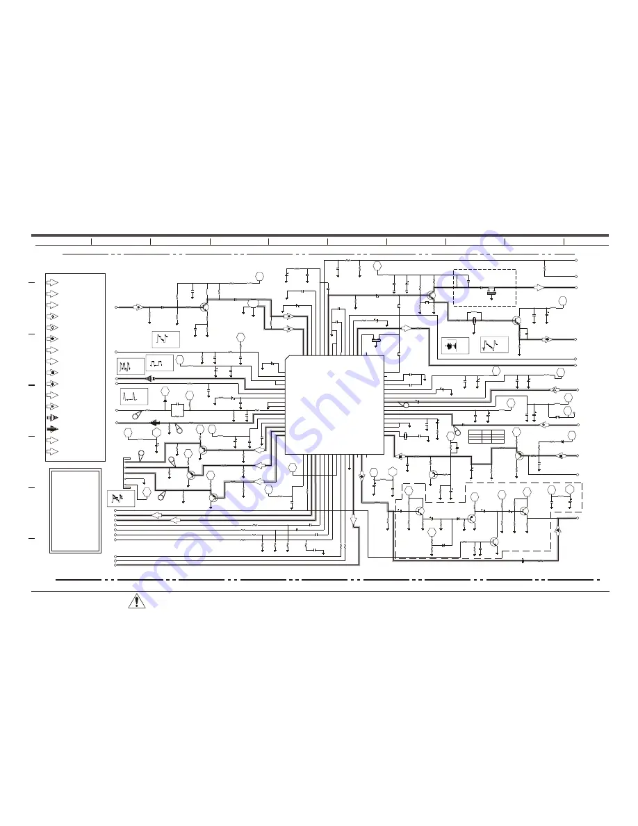
Video Processor Circuit

IF

Vertical

Horizontal

H-SYNC

H-SYNC

V-SYNC

V-SYNC

V-Sync

H-Sync

Subcarrier Signal

FSC

FSC

Luma (Micro)

ABL

Chroma (C-IN)

Luma (Y-IN)

Composite Video IF

G

G

R

R

B

B

Red

Blue

Green

SIF

SIF

Sound IF

Composite Audio

((

(( ( ( ( (

This schematic refers to 

CL Chassis models

H19F34DT
H20F34DT
H25F34DT
H25F39DT
H27F34DT
H27F39DT
H25F36DT
H27F36DT
H32F36DT

CRITICAL SAFETY COMPONENTS ARE IDENTIFIED BY THE LETTER “X” IN THEIR
COMPONENT DESIGNATORS. REPLACE ONLY WITH PART NUMBERS SPECIFIED.

ALL SYMBOLS WITH “M” ON THE DESIGNATOR
INDICATE SURFACE MOUNTED COMPONENT.

6-4

WF10

5.26 V

10.0 µS

WF9

V

10.0 

µ

S

WF12

1.55 V

10.0 µS

WF13

40.8 V

10.0 µS

WF11

5.18 V

10.0 µS

WF14

1.044 V

10.0 µS

WF15

580mV

10.0 µS

SR25-3828VD0171B

Summary of Contents for H19F34DT Series

Page 1: ...ing Model Module Parts List Exploded Views Schematics Published by Technical Publications Zenith Electronics Corporation P O Box 240007 Huntsville Al 35824 Copyright May 2005 by Zenith Electronics Cor...

Page 2: ...pe conduit etc and the exposed metallic parts one at a time Measure the AC voltage across the combination of 1500 ohm resistor and 15mfd capacitor Reverse the AC plug by using a non polarized adaptor...

Page 3: ...e following procedure Measurement of the CRT anode voltage must be performed using a high impedance high voltage meter with no raster on the screen and operating at nominal horizontal frequency 15 75...

Page 4: ...ERVICING SERVICING 3 1 GENERAL INFORMATION 3 1 MODULE LEVEL SERVICING 3 1 SERVICING THE POWER SUPPLY 3 1 IF SERVICING 3 4 AGC DELAY 3 4 G2 ADJUSTMENT 3 4 FOCUS ADJUSTMENT 3 4 ADJUSTMENT OF RGB CUTOFF...

Page 5: ...ing IC2902 Y C switch IC2800 Audio switch MODEL SCR FRONT JACKS REAR JACKS AUDIO EXTRA FEATURES REMOTE MICRO OP GUIDE H19F34DT 19 N A 3 MONO SuperPort Slot MPI Card 6710V00108A 0IMCRMI038A 3828VA0A30A...

Page 6: ...receivers are now being adapted to interact with other equipment Prime examples of this can be found in Lodging and Health Care situations where the set is controlled from the main office All this is...

Page 7: ...programmer page 1 5 for programming other TVs in the system with the same features as the master TV 4 S VIDEO IN AND OUT These jacks are for input and output connections to SUPER VHS video equipment U...

Page 8: ...ARM Press to turn wake up alarm ON or OFF ENTER Press to view Channel Time or to remove any on screen display in TV mode Display menu or POWER Press to turn TV ON or OFF CC Press to access closed capt...

Page 9: ...creen displays LEARNING COMPLETED press any key to end the learning process and return to the clone selection menu WRITE TO TV Select WRITE TO TV and then press ON OFF POWER or ENTER to begin teaching...

Page 10: ...CHANNEL DOWN keys to highlight your choice Then press ON OFF POWER or ENTER The TV screen will display the items in the service menu setups Use this function to quickly check the TV for correct setup...

Page 11: ...at the SETUP MENU reappears Use the Up Arrow to choose the CH LABELS option Pressing either the Right Left arrow re peatedly pick the label you want from the list of avail able selections shown in the...

Page 12: ...Sets a time that the TV will turn itself On each day Off Time Sets a time that the TV will turn itself Off each day On Off Timer Enables or disables the On Off Timer functions The On Off Timer can be...

Page 13: ...the Preset setting and the customer sets custom Press a RIGHT LEFT ADJ arrow to adjust or change the op tion you have selected Press ENTER to return to TV view ing or press the Up Arrow to adjust ano...

Page 14: ...SOURCES unblocked and then choose allowable ratings In the CONTENT BLK option you can block program Content based on individual parameters such as Strong Dialog Bad Language Sex Scenes Violence Scene...

Page 15: ...that parents may not want their children to view the program Suggested PG 13 Parental Guidance Program is inappropriate for preteens with a greater degree of offensive Suggested material than a PG rat...

Page 16: ...RCE MENU Scrolling the menus using the Menu key can access the Source Menu ANTENNA CABLE CAMPORT S VIDEO AUX VIDEO SOURCE MENU PRESS TO CHANGE PRESS ENTER OR KEYS TO ACTIVATE Use the Up Down Arrows to...

Page 17: ...he SELECT UP DOWN keys to toggle through all of the adjustments Use ADJUST to make a change to the selected item INSTALLERS MENU OPTIONS 0 I INSTALLER SEQ Range is 0 3 Determines the Se quence used to...

Page 18: ...ctory default is 0 It may be best to set the same value on every TV Note The minimum volume level cannot have a value setting higher than in the MAX VOLUME level described below 9 I MAX VOLUME This fu...

Page 19: ...s item is generally set to off so it can be controlled with entertainment unit In off mode Auto Program and Channel Add Delete do not function Changing to channels not added in the favor ites list wit...

Page 20: ...use custom colors for Audio Menu Zero is disable and 1 is enable 58 I FOR AUDIO M Select between 0 to7 to set fore ground color for Audio Menu See Table 1 59 I BCK AUDIO M Select between 0 to7 to set...

Page 21: ...his number is displayed at the lower part of the Installers Factory Menu Range is 0 255 81 I UPN LSB User definable number least significant byte readable by MPI command This number is displayed at th...

Page 22: ...9 I NOT USED 20 I FEATURE LEVEL 0 1 1 Zen 1 Leave default set to 1 1 Zen 1 21 I V CHIP 0 1 1 Set to 1 to enable V Chip 22 I MAX BLK HRS 0 99 12 Select number of Parental Control blocking hours 23 I CA...

Page 23: ...SCR M 0 7 4 Custom background color for the Source menu 69 I EN CH T COL 0 1 1 Set to 1 to enable custom color for the Channel Time display 70 I FOR CH T COL 0 7 1 Custom foreground color for the Chan...

Page 24: ...The Range is from 0 30 This adjustment is generally set at 15 4 F H0RZ POS Moves On Screen Displays horizontally Range is from 1 45 5 F RF DELAY ADJ RF automatic Gain Control Range is from 0 127 35 is...

Page 25: ...the typical setting is at 9 39 F V PHASE Vertical Phase adjustment The Range 0 7 is typically set to 1 40 F AFC1 GAIN Horizontal AFC1 Gain switch The range is 0 1 41 F AFC2 GAIN Horizontal AFC2 Gain...

Page 26: ...ing adjustments for Trap 3 58 27 F RF Y DLTIME 0 6 3 2 2 3 3 3 3 Luma delay time adjustments for RF Mode 28 F RF CHROMA BP 0 1 1 1 1 1 1 1 1 Band Pass filter for RF Mode 29 F AUX Y DL TIME 0 7 3 2 2 3...

Page 27: ...lays vertically The Range is from 0 30 This adjustment is generally set at 15 03 F H0RZ POS Moves On Screen Displays horizontally Range is from 0 45 04 F RF DELAY ADJ RF automatic Gain Control Range i...

Page 28: ...he range is 0 1 typically set to 0 34 F SLICE DOWN1 Sync det slice level section The range is 0 1 typically set to 0 35 F SLICE DOWN2 Sync det slice level switch The range is 0 1 typically set to 0 36...

Page 29: ...UX 0 7 3 3 Luma delay time for Aux Mode 22 F CHROMA BP AUX 0 1 0 0 Bandpass filter for Aux Mode 23 F AUX SUBTINT 0 15 13 13 Subtint Adj for Aux Mode 24 F CKILL LEVEL 0 1 0 0 Color killer level 25 F YS...

Page 30: ...deo output module from the CRT when troubleshooting 32 receiv ers If the video output module is removed on these sets while power is ON the CRT will arc and can be permanently damaged Also the technic...

Page 31: ...ed by TX3204 Precision resistors RX3013 RX3015 RX3016 and RX3022 divide this voltage down This lower voltage appears on the input QX3002 collector of a comparator circuit formed by RX3008 ZDX3004 QX30...

Page 32: ...her than the maximum verify circuit component values and proper operation CRT Screen Size Nominal Anode Voltage KV Max Shutdown Voltage KV 19 26 1 0 32 20 26 1 0 32 24 25 28 1 0 34 27 28 1 0 34 32 30...

Page 33: ...cus potentiometer to obtain the best fo cus at letters of menu ADJUSTMENT OF RGB CUTOFF Note If the Main Module or the CRT has been replaced G2 must be readjusted before adjusting the RGB Cutoff 1 Ent...

Page 34: ...processor SENSING AND PRIORITIES CL Series 34 39 models do not have a source menu Software sensing the inputs based on their priorities does switching between sources The camport input always has fir...

Page 35: ...verge the red and blue lines horizontally Move the two tabs together around the neck of the CRT in a 45 arc from the top dead center position to converge the red and blue lines vertically b After the...

Page 36: ...irection to obtain convergence In such cases insert the vertical tilt wedge at the bottom 6 o clock position Follow through on the horizontal tilt adjustment by using the 2 and 10 o clock positions an...

Page 37: ...08A Space Command Transmitter Remote Controller 6710V00108A Space Command Transmitter Remote Controller 5016V20002A Convergence Helper 5016V20002A Magnet Stick Ferrite Convergence Helper Item number P...

Page 38: ...with Deflection Yoke 6411VUH003A Power Cord Assembly Line Cord and Terminals Assembly 170 844J CPT Earth_Gnd Strap Assy CRT 6335V27001A CPT Assembly with Deflection Yoke 3141VSNC61C Keyboard Assy 6 Ke...

Page 39: ...per 3790V00711A Crystal Window 3828VA0A30N Instr Book Operation Guide 6411VUH003A Power Cord Assembly Line Cord and Terminals Assembly 6335V24002A CPT Assembly with Deflection Yoke 170 844G CPT Earth_...

Page 40: ...NS 3790V00712A 5 CPT YOKE ASSEMBLY 6335V20A03A 6 REAR CABINET BACK COVER ASSEMBLY 3809V00B08B 7 MAIN MODULE CHASSIS ASSEMBLY 3141VMNP44A 8 REMOTE CONTROL 6710V00108A Cl Commercial 19 Exploded View 5 1...

Page 41: ...CABINET CABINET ASSEMBLY 3091V00485A 2 SPEAKER SPEAKER FULL RANGE 6400VESU01A 3 KEYBOARD ASSEMBLY 3141VSNC61B 4 IR LENS 3790V00715A 5 CPT YOKE ASSEMBLY 6335V20A03A 6 REAR CABINET BACK COVER ASSEMBLY 3...

Page 42: ...ET ASSEMBLY 3091V00B80A 3091V00B80A 3091V00B80A 2 SPEAKER SPEAKER FULL RANGE 120 C77G 120 C77G 120 C77G 3 KEYBOARD ASSEMBLY 3141VSNC61C 3141VSNC61C 3141VSNC61C 4 WINDOW 3790V00711A 3790V00711A 3790V00...

Page 43: ...3091V00B80A 3091V00B80A 2 SPEAKER SPEAKER FULL RANGE 6400VSNX01A 6400VSNX01A 6400VSNX01A 3 KEYBOARD ASSEMBLY 3141VSNC61C 3141VSNC61C 3141VSNC61C 4 IR LENS 3790V00711A 3790V00711A 3790V00711A 5 CPT YOK...

Page 44: ...EAKER SPEAKER FULL RANGE 6400VSNX01A 6401VC0134J 6401VC0134J 6400VSNX01A 3 KEYBOARD ASSEMBLY 3141VSNC61C 3141VSNC61C 3141VSNC61G 3141VSNC61C 4 IR LENS REMOTE CONTROLLER RECEIVER 6712SCA227A 6712SCA227...

Page 45: ...CL EXPLODED VIEW REF DESCRIPTION H32F36DT 1 FRONT CABINET CABINET ASSEMBLY 3091V00B56A 2 SPEAKER SPEAKER FULL RANGE 6400VSNX01A 3 KEYBOARD ASSEMBLY 3141VSNC61C 4 IR LENS 3790V00711A 5 CPT YOKE ASSEMBL...

Page 46: ...W RX3810 2W 2 2 CX3822 16V 220 F CX3811 16V 470 F ICX3810 KIA78R09PI GND GND OUT IN CTL CTL 0IMCRKE002A 408 002F 4921V00163A ZDX3821 MTZ5 1B 1 2W 5 1V 0DZ510009AB ICX3830 KIA78R08PI GND GND OUT 8V IN...

Page 47: ...pF CM6005 50V 220pF CM6007 1000pF 50V CM6010 50V 20pF CM6011 50V 20pF CM6012 25V 0 01 CM6014 50V 27pF CM6015 50V 27pF CM6017 16V 0 1 CM6018 1000pF 50V CM6019 50V 180pF CM6021 25V 0 01 CM6023 50V 47pF...

Page 48: ...LA7845 KTA1046YU 0TR104600AB QX3251 E B C 0ISA784500AA 4920V00008D QX3251 4921V00N11U R3253 2 7K 1 2W CX3004 50V 10 F QX3002 E B C KSA733C Y 0TR733009AA DX3006 0DR150009EA RGP15J QX3001 E B C KSC945C...

Page 49: ...O IN AUDIO OUT B OUT G OUT R OUT INTERCARRIER OUT CHROMAAPC FILTER VIDEO CHROMA GND ACL ABCL DRIVE GND 42 52 53 54 55 LIMITER IN 56 57 58 59 60 61 62 63 64 HVCO FEED BACK NC 8 7V REG OUT INT MON VIDEO...

Page 50: ...3 3 F Q1401 E B C KSA733C Y 0TR733009AA Q1400 E B C KSA733C Y 0TR733009AA R2800 PROV R2801 PROV R1401 100 R1402 100 R2812 2 2K R2802 2 2K R2803 2 2K Q1402 E B C KSC945C Y 0TR945009AA C1426 16V 47 F R...

Page 51: ...6 MATRIX OUT 2 Y C IN 14 LEFT IN LEFT IN RIGHT IN 24 10 8 4 12 11 5 16 13 C 9 19 Y 15 3 1 21 18 17 23 RIGHT IN VIDEO IN 22 20 JP1 P L JM2471 P L JM2901 P L JM2902 P L JM2903 P L JM2904 P L ZD2800 PROV...

Page 52: ...22K SBF 5V 58 661 10K 121 1310A R4982 R4989M R4984 R4987 W12VRJ11 R4994M R4985M R4996 MPI C4946 R4983 Q4905 R4991 R4990 Q4904 6E2 R4992 R4995M R4993 C4967 C4966 Q4903 C4965 R4986M 11E1 R4997 Q4906 1 2...

Page 53: ...1 2W 1K 1 P L R5112 C5104 2 C5105M R5129 Q5104 Q5102 C5118M C5103M R5124M C5110 L5102 D5102 C5111 DAG R5114 W5102 Q5101 R5118M R5110 C5106M R5103 DAG1 R5115 R5123 RX5104 RX5111 RX5122 C5109M R5119 5C2...

Page 54: ...TA_IN SPI_DATA_IN SPI_CLOCK SPI_CLOCK BUFFERED_IR_DATA_OUT BUFFERED_IR_DATA_OUT CLONESENSE PTY_SELECT CLONESENSE PTY_SELECT 11V 11V SYNC_GND 58 542 10 P078 3571 58 593 10 P078 3571 P078 3571 P078 3571...

Page 55: ...10 IC800 4920V00010 0ISA426100A LA4261 4921V00N11Q CM827 5600pF 50V RM825 3K RM826 4 7K CM801 25V 0 01 CM830 25V 0 01 RM811 3 9K RM821 3 9K RM812 1 8K RM822 1 8K RM813 150 RM823 150 TP800 TP801 TP802...

Page 56: ...CM2401 50V 12pF CM2403 50V 27pF CM2402 50V 27pF CM2404 25V 0 01 CM2405 25V 0 01 CM2407 25V 0 01 CM2411 25V 0 01 CM2415 50V 120pF CM2416 50V 180pF CM2417 25V 0 01 CM2418 25V 0 01 CM2426 25V 0 01 RM240...

Page 57: ...TAL COUNT DOWN V COINB V SHIFT V SIZE AFC 2 Intelligent Monitoring Intelligent Monitoring I I VCO AFC I AFC GAIN I I COINCI Hi Vcc H COINB I I pHASE NC H STOP DEF Vcc 8V V PULSE OUT VERTICAL V OUT DY...

Page 58: ...CX3816 CX3813 RX3505 W11 DX3813 RX3816 RX3815 W130 FRX3815 W118 W12 CX3811 QX3505 E B C W113 W110 W80 CX3831 CX3841 ICX3840 IN OUT GND LX3840 RX3820 ZDX3826 ZDX3821 ICX3830 GND OUT IN CTL W135 RX3810...

Page 59: ...R3203 C3202 W15 W16 W147 CX3007 DX3006 DX3251 CX3256 CX3252 DX3900 E B C QX3900 C2406 C3250 W129 R2226 R3251 CX3822 RX3811 W126 RX3832 W109 CX3836 CX3854 RX3852 RX3851 RX3850 RX3611 CX3853 W149 W148 W...

Page 60: ...Q4905 W5102 R5103 R5115 W201 R5123 DAG1 R5119 R5110 R5127 Q4904 C5111 W5103 DAG2 R5112 R5126 W200 R5105 R5120 R4984 W12VRJ11 R4982 CON2 Q4903 W0162 W0161 2E6 CON1 1E11 2VGA8 W0163 R5125 R5107 W5100 W...

Page 61: ...R5113M R5121M R5105M R5112M R5120M R5108M R5117M R5102M R5101M PCB Bottom Layout CRITICAL SAFETY COMPONENTS ARE IDENTIFIED BY THE LETTER X IN THEIR COMPONENT DESIGNATORS REPLACE ONLY WITH PART NUMBERS...

Page 62: ...z e n i t h...

Reviews: