SR25-3828VD0171B
Y/C-SENSE
CAMPORT-SENSE
TV
AUX-LEFT-Y/C
AUX-RIGHT-VID
AUX-LEFT-VID
C-MAIN
Y-MAIN
CTRL-Y/C
CTRL-TV/AUX
CTRL-F/R
AUX-RIGHT-Y/C
MATRIX/SPEAKER-OUT
CV-COMB
LUMA-COMB
CHROMA-COMB
AUD-LEFT-FRONT
AUD-RIGHT-FRONT
SWF
+9V
+9VSWF
+9V
SWF
SWF
+9V
SWF
+9V
SWF
+9V
SW
+9V
SW
+9V
L2471
P/L
L2900
10µH
C2802
50V
1µF
C2804
50V
1µF
C
H
-1
C
H
-2
12
11
10
9
8
7
6
5
4
3
2
1
IC2901
LA7222
0ISA722200A
C
H
-1
C
H
-2
12
11
10
9
8
7
6
5
4
3
2
1
IC2902
LA7222
0ISA722200A
C2805
50V
1µF
C2901
50V
10µF
C2903
50V
10µF
C2803
50V
1µF
C2474
50V
10µF
C2904
50V
10µF
C2900
16V
100µF
C2905
50V
10µF
Q2902
E
B
C
KSC945C-Y
0TR945009AA
Q2901
E
B
C
KSC945C-Y
0TR945009AA
C2902
50V
10µF
C2908
50V
PROV
C2909
50V
PROV
C2910
50V
PROV
ZD2903
MTZJ9.1B
1/2W
9.1V
0DZ910009AJ
ZD2901
MTZJ9.1B
1/2W
9.1V
0DZ910009AJ
ZD2902
MTZJ9.1B
1/2W
9.1V
0DZ910009AJ
CM2907
PROV
50V
CM2911
PROV
50V
R2808
PROV
R2810
PROV
R2804
PROV
R2806
PROV
R2912
22K
R2807
2.2K
R2805
2.2K
R2906
75
R2905
47
R2902
75
R2904
75
R2903
47
R2901
47
R2910
22K
R2909
22K
R2911
22K
RM2482
PROV
R2917
1K
R2916
1K
L2481
P/L
R2930
2.2K
R2926
1K
1
2
3
4
5
8
7
6
CN4B8
366-921G
R2907
100
R2908
75
ZD2904
MTZJ9.1B
1/2W
9.1V
0DZ910009AJ
7,
6
MATRIX
OUT
2
Y/C
IN
14
LEFT
IN
LEFT
IN
RIGHT
IN
24
10
8
4
12
11
5
16
13
C
9
19
Y
15
3
1
21
18
17
23
RIGHT
IN
VIDEO
IN
22
20
JP1
P/L
JM2471
P/L
JM2901
P/L
JM2902
P/L
JM2903
P/L
JM2904
P/L
ZD2800
PROV
R2811
6.8K
R2809
6.8K
CM2471
50V
100pF
CM2906
16V
0.1
RM2471
P/L
RM2472
0
RM2481
100
RM2918
100
RM2919
10K
RM2920
0
RM2921
1K
RM2922
1K
RM2923
0
RM2924
100
RM2925
10K
CM2482
50V
P/L
CM2483
25V
P/L
CM2472
50V
PROV
CM2473
P/L
50V
RM2473
4.7K
CM2481
50V
P/L
NO
COMB
CM2472
WITH
COMB
4.7K
33
4.7µH
180pF
RM2473
RM2471
Y/C
MODELS
ONLY
L2471
CM2473
270pF
OUT
JM2903
Y/C
INPUT
JM2901
C2474
JM2471
IN
OUT
JM2902
OUT
NO Y/C
INPUT
IN
OUT
IN
IN
OUT
IN
IN
OUT
JM2904
A1R
A1R
A1L
A1L
M-OUT
M-OUT
A3R
A3R
A3L
A3L
1
2
3
4
5
6
7
8
9
10
G
D
C
B
E
F
A
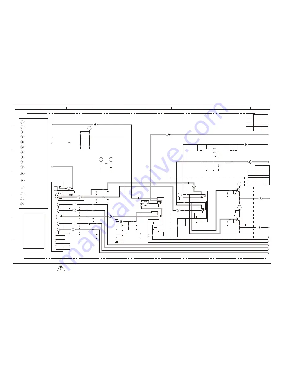
A/V Switch Circuit
Composite Video
Switch
Chroma-Comb (C-IN)
Luma-Comb (Y-IN)
A1R
A1L
M-OUT
Aux1-R
Aux1-L
Matrix-Speaker
Out
A3R
A3L
Aux3-L
Aux3-R
Composite Video IF
Luma Rear (Y-IN)
Chroma Rear (C-IN)
Luma (Y-IN)
Chroma (C-IN)
Composite Video
“Comb-Filter”
Composite Video
“Rear”
Composite Video
“Camport”
This schematic refers to
CL Chassis models
H19F34DT
H20F34DT
H25F34DT
H25F39DT
H27F34DT
H27F39DT
H25F36DT
H27F36DT
H32F36DT
CRITICAL SAFETY COMPONENTS ARE IDENTIFIED BY THE LETTER “X” IN THEIR
COMPONENT DESIGNATORS. REPLACE ONLY WITH PART NUMBERS SPECIFIED.
ALL SYMBOLS WITH “M” ON THE DESIGNATOR
INDICATE SURFACE MOUNTED COMPONENT.
6-6
Summary of Contents for H19F34DT Series
Page 62: ...z e n i t h...