3-16
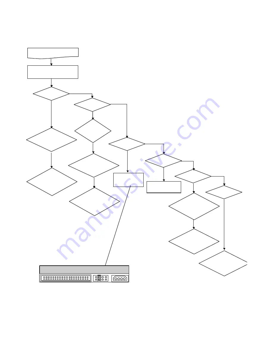
7) PVR PART
Yes
No
No
When TV is normally operated
but PVR does not function
"PVR function doesn't work
properly" of the SETUP menu.
Error code
= 121
Check PCI Clock
Check 33.33MHz output
at IC102 8-Pin
Check IDSEL
Check whether IC134
17-Pin is high at
Configuration cycle
Error code
= 124
Check
HDD Cable and
HDD Power Cable
connection
Check PCI Clock
Check 33.33MHz output
at IC102 8-Pin
Check IDSEL
Check whether IC140
16-Pin is high at
Configuration cycle
Error code
= 125
HDD Jumper
Check Setting
Error code
= 131
Error code
= 132
Check
PDR-Pro Clock
Check 33.33MHz output
at IC134 220-Pin
Down
Check SDRAM
Check 33.33MHz output
at IC137 68-Pin
Up
Check SDRAM
Check 33.33MHz output at
IC136 68-Pin
Error code
= 133
Check the operation
of the VSB section by
referring to the figure
Summary of Contents for HDR230
Page 28: ......
Page 34: ......
Page 37: ......
Page 38: ...3 17 3 18 4 WAVEFORMS 1 DIGITAL SYSTEM CLOCK GENERATOR PART 1 2 3...
Page 39: ...3 19 3 20 2 DIGITAL SYSTEM SYSTEM MEMORY PART 1 2 3...
Page 40: ...3 21 3 22 3 VIDEO PLL PART 1 2...
Page 41: ...3 23 3 24 4 VIDEO OUTPUT CONNECTOR PART 1 2 3 BMK800 BMK800 BMK800 33PF 33PF 33PF...
Page 43: ...3 27 3 28 6 PVR CLOCK PART 1 2 3...
Page 44: ...3 29 3 30 7 VSB VSB DECODER PART 1...
Page 45: ...3 31 3 32 8 VSB DOWN CONVERTER PART 1...
Page 46: ...3 33 3 34 9 MICOM DOWN CONVERTER PART 1...
Page 47: ......
Page 65: ...3 74 3 75 10 VSB CIRCUIT DIAGRAM IF VSB TP Data clock error valid 03 3 15 HDR230 DNS...
Page 67: ...3 78 3 79 12 POWER IF COM VIDEO CIRCUIT DIAGRAM CVBS OUT Y OUT C OUT 03 3 15 HDR230...
Page 68: ...3 80 3 81 13 FRONT CIRCUIT DIAGRAM RIGHT LEFT 03 3 15 HDR230...
Page 69: ...3 82 3 83 8 PRINTED CIRCUIT DIAGRAMS 1 DIGITAL MAIN PRINTED CIRCUIT DIAGRAMS TOP...
Page 70: ...3 84 3 85 2 DIGITAL MAIN PRINTED CIRCUIT DIAGRAMS BOTTOM...
Page 72: ...3 88 3 89 5 POWER PRINTED CIRCUIT DIAGRAM LOCATION GUIDDE...


