background image

Owner’s Manual   25

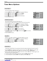
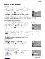
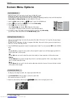
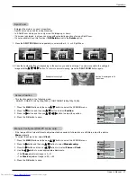
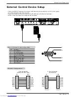
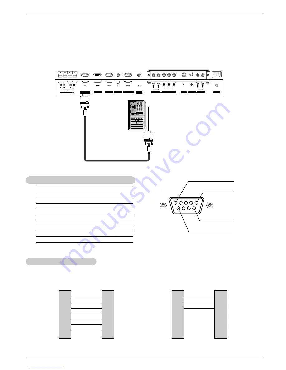
External Control Device Setup

No. Pin 

Name

1 No 

Connection

2

RXD (Receive data)

3

TXD (Transmit data)

4

DTR (DTE side ready)

5

GND

6

DSR (DCE side ready)

7

RTS (Ready to send)

8

CTS (Clear to send)

9

No Connection

1

5

6

9

2
3
5
4
6
7
8

RXD

TXD

GND

DTR

DSR

RTS
CTS

TXD

RXD

GND

DSR

DTR
CTS

RTS

PC

7-Wire Configuration

(Standard RS-232C cable)

D-Sub 9

3
2
5
6
4
8
7

PDP

D-Sub 9

2
3
5
4
6
7
8

RXD

TXD

GND

DTR

DSR

RTS
CTS

TXD

RXD

GND

DTR

DSR

RTS
CTS

PC

3- Wire Configuration

(Non standard)

D-Sub 9

3
2
5
4
6
7
8

PDP

D-Sub 9

- Connect the RS-232C input jack to an external control device (such as a computer or an A/V control system)

and control the Monitor’s functions externally.

- Connect the serial port of the control device to the RS-232C jack on the Monitor's back panel.
- RS-232C connection cables are not supplied with the Monitor.

T

T

ype of Connector: D-Sub 9-pin Male

ype of Connector: D-Sub 9-pin Male

RS-232C Configurations

RS-232C Configurations

External Control Device Setup

External Control Device Setup

R

(  )

(  )

(  )

(  )

L

RS-232C INPUT

(CONTROL/SERVICE)

EXTERNAL SPEAKER

Y

P

B

P

R

(MONO)

R

AUDIO

L

R

AUDIO

L

S-VIDEO

AC INPUT

AUDIO INPUT

VIDEO INPUT

AUDIO INPUT

AUDIO INPUT

REMOTE

CONTROL

COMPONENT INPUT

DVI INPUT

RGB INPUT

RGB OUTPUT

Downloaded from 

www.Manualslib.com


manuals search engine


Summary of Contents for P50W38

Page 1: ...Copyright 2003 Zenith Electronics Corporation Installation and Operating Guide Model Numbers P50W38 P50W38H P50W38P PLASMA DISPLAY PANEL Downloaded from www Manualslib com manuals search engine...

Page 2: ...nterference to radio communications However there is no guarantee that interference will not occur in a particular installation If this equipment does cause harmful interference to radio or television...

Page 3: ...hould follow the manufacturer s instructions and should use a mounting accessory recommended by the manufac turer 8 Transporting Product A product and cart combination should be moved with care Quick...

Page 4: ...oints or short out parts that could result in a fire or electric shock Never spill liquid of any kind on the product 19 Servicing Do not attempt to service this product yourself as opening or removing...

Page 5: ...21 Screen Adjustments 22 Initializing 22 Selecting Wide VGA XGA mode 22 Luminance Noise Reduction 22 PIP Picture in Picture Feature Watching PIP 23 PIP Size 23 PIP Aspect Ratio 23 Swapping PIP 23 Mov...

Page 6: ...ent on the PDP screen The PDP Plasma Display Panel which is the display device of this product is composed of 0 9 to 2 2 million cells A few cell defects will normally occur in the PDP manufacturing p...

Page 7: ...te control port on the Monitor 6 COMPONENT INPUT AUDIO INPUT JACKS Connect a component video audio device to these jacks 7 S VIDEO INPUTS Connect S Video out from an S VIDEO VCR or other S Video devic...

Page 8: ...nu NUMBER buttons WIN SIZE Adjusts the sub picture size WIN POSITION Moves the sub picture SPLIT ZOOM Enlarges the picture ZOOM ZOOM Enlarges or reduces the main picture size VCR BUTTONS Control some...

Page 9: ...tc The plasma display is designed to be mounted horizontally or vertically The speakers shown are optional GROUNDING Ensure that you connect the grounding earth wire to prevent possible electric shock...

Page 10: ...hange the OSD display mode so that the menus will appear correctly and also to protect the monitor from overheating Refer to P 19 2 inches 4 inches 2 36 inches 4 inches 4 inches Desktop Pedestal Insta...

Page 11: ...the VCR owner s manual 2 Use the INPUT SELECT button on the remote control to select Video If connected to S VIDEO select the S Video input source VCR Setup VCR Setup S VIDEO OUT IN R AUDIO L VIDEO Y...

Page 12: ...ernal equipment operating guide Component ports of the Monitor Y PB PR Video output ports of DVD player Y Y Y Y Pb B Y Cb PB Pr R Y Cr PR How to connect 1 Connect the DVD video outputs to the COMPONEN...

Page 13: ...brightness in PC mode If noise is present change the PC mode to another resolution change the refresh rate to another rate or adjust the brightness and contrast on the menu until the picture is clear...

Page 14: ...0 31 75 00 85 06 74 55 60 00 70 00 75 00 31 500 35 000 37 500 48 363 56 476 60 023 54 348 63 995 67 500 60 000 63 981 47 700 59 625 47 700 59 625 60 00 70 00 75 00 60 00 70 06 75 02 60 05 70 01 75 00...

Page 15: ...rned off with the ON OFF button on the Monitor 2 If the Monitor was turned off with the remote control and then the ON OFF button on the Monitor Press the ON OFF button on the Monitor and then press t...

Page 16: ...pness and tint manually APC automatically changes the setting to User You can adjust red green and blue to any color temperature you prefer 1 Press the MENU button and then use D E button to select th...

Page 17: ...he program content When adjusting sound options treble bass and balance manually DASP automatically changes to User This feature maintains an equal sound level even if you change channels 1 Press the...

Page 18: ...Auto off On Off Vol MENU Prev VIDEO AUDIO TIME SCREEN TWIN SPECIAL Clock Off timer On timer Auto off G On Off MENU Prev Clock Setup Clock Setup If current time setting is wrong reset the clock 1 Press...

Page 19: ...ock On if the monitor is turned off with the remote control press the INPUT SELECT button on the monitor or POWER or INPUT SELECT on the remote control to turn the monitor on W Normal Rotate A frozen...

Page 20: ...s shown with gray bars at the sides of the screen for a long time the gray images may remain visible All aspect ratio for RGB 480p DVI 480p Component 480i 480p Video and S Video sources are shown belo...

Page 21: ...he MENU button and then use D E button to select the SCREEN menu 2 Press the G button and then use D E button to select Position 3 Press the G button and then use D E F G button to adjust the position...

Page 22: ...A mode automatically VIDEO AUDIO TIME SCREEN TWIN SPECIAL Auto config ARC Zoom in out Position Manual config Screen adj Reset XGA Mode G 1024x768 1360x768 1366x768 MENU Prev VIDEO AUDIO TIME SCREEN TW...

Page 23: ...es up down left right Swapping PIP Swapping PIP Press the SWAP button to switch the main and sub pictures Selecting an Input Signal Source for the PIP Selecting an Input Signal Source for the PIP Use...

Page 24: ...Picture win Picture Use the SWAP button to switch the main and sub pictures in twin picture mode DW 1 DW 2 10 30 10 30 Component Video Video Component As the name suggests this mode splits the screen...

Page 25: ...32C input jack to an external control device such as a computer or an A V control system and control the Monitor s functions externally Connect the serial port of the control device to the RS 232C jac...

Page 26: ...64 11 Sharpness k k 0 64 12 OSD Select k l 0 1 13 Remote Control Lock Mode k m 0 1 14 PIP Twin k n 0 3 15 PIP Aspect Ratio k o 0 1 16 Split Zoom k p 0 99 17 PIP Position k q 0 3 18 Treble k r 0 64 19...

Page 27: ...een Zoom 3 Horizon k c Set ID Data Cr Acknowledgement You select either 16 9 or 4 3 screen aspect ratio using the PC DTV 720p 1080i c Set ID OK Data x 05 Volume Mute Command2 e G To control volume mut...

Page 28: ...an also select the PIP picture format using PIP ARC on the remote control Transmission k o Set ID Data Cr Acknowledgement Data 0 4 3 1 16 9 o Set ID OK Data x 09 Color Command2 i G To adjust the scree...

Page 29: ...the Audio menu Transmission Data Min 0 Max 64 Refer to Real Data Mapping 1 See page 27 k s Set ID Data Cr Acknowledgement s Set ID OK Data x 20 Balance Command2 t G To adjust balance You can also adj...

Page 30: ...ta 1 To set j u Set ID Data Cr Acknowledgement u Set ID OK Data x 31 Picture Size Setting for Twin Picture mode Command2 t G To adjust main picture size in twin picture mode Transmission Data Min 0 Ma...

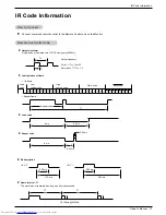
Page 31: ...requency FCAR 1 TC fOSC 12 Duty ratio T1 TC 1 3 Repeat frame C1 C2 C3 C4 C5 C6 C7 C0 C1 C2 C3 C4 C5 C6 C7 D0 D1 D2 D3 D4 D5 D6 D7 D0 D1 D2 D3 D4 D5 D6 D7 Repeat code 9 ms 4 5 ms 0 55 ms 9 ms 2 25 ms G...

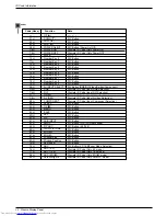
Page 32: ...er On Off Discrete IR Code Only Power On Discrete IR Code Only Power Off R C Button R C Button R C Button R C Button R C Button R C Button R C Button R C Button R C Button R C Button R C Button R C Bu...

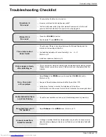
Page 33: ...he Monitor and the VCR Activate any function to restore the brightness of the picture If still picture is on the screen for more than 5 minutes the screen gets dark The remote control doesn t work Che...

Page 34: ...Early malfunctions can be prevented Careful and regular cleaning can extend the amount of time you will have your new Monitor Be sure to turn the power off and unplug the power cord before you begin...

Page 35: ...d circumstances shall be borne by the consumer WARRANTY PERIOD LABOR ONE YEAR from the Date of Purchase PARTS ONE YEAR from the Date of Purchase Effective Date of Warranty Your warranty period Begins...

Page 36: ...urning the defective unit to Zenith Parts and service in accordance with the Zenith warranty are Zenith s responsibility and will be provided without charge Other service requirements will be at the o...

Reviews: