Zenith
®
Pumps and The Extrusion Process
Design
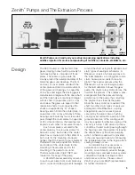
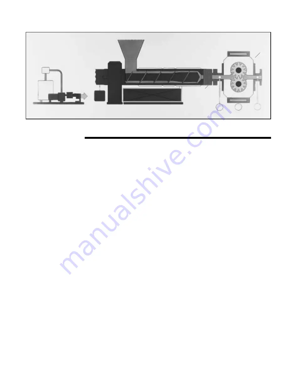
Zenith Pumps can handle all your extrusion pumping applications including
additive injection for on-line compounding of tackifiers, colorants, stabilizers, etc.
3
ZENITH
ADDITIVE
INJECTION
SYSTEM
ELECTRIC
HEAT PLATE
PUMP
TEMPERATURE
INLET
PRESSURE
DISCHARGE
PRESSURE
ZENITH
PEP-II
PUMP
CHANGER
P
P
T
EXTRUDER
The PEP-II pump is constructed of two
gears rotating in mesh within a closely fit-
ted housing that is comprised of three
plates. The center, or gear plate, fits
closely around the outside diameter of the
metering gears and bearings. The front
and rear, or cover plates, sandwich the
center plate and restrict axial movement
of the gears and bearings. In capacities
of 5 cc/rev and larger, the driving gear is
manufactured integral with the drive shaft,
and the driven gear is machined integral
with its shaft. In capacities of 3.0 cc/rev
and below, the gears are keyed to their
respective shafts. In all capacities the
shafts are supported by “D” shaped
bearings which fit into the center plate. In
capacities of 40 cc/rev and above, these
bearings are located by two screws which
pass through the cover plates. In capacities
of 20 cc/rev and below, the bearings are
keyed to each other for accurate location.
Each cover plate is secured to the
center plate by 10 screws (6 screws for
below 5 cc/rev). Each side of the center
plate has a circular port in the center of a
bolt circle for the mounting of adapter
flanges that fit the pump to your equiment.
Threaded holes are provided on the top
and bottom of the center plate for the
mounting of heat plates and for the
mounting of the pump to its stand.
Thermocouple wells (1/8-27 NPT) are
located on the body of the pump.
A Zenith Rheoseal assembly secured
to each cover plate (front cover plate only
on 3.0 cc/rev and below) prevents leakage
around the shaft, using both dynamic and
static types of sealing mechanisms. A
Rheoseal consists of a helical groove on
the inner diameter, a cooling jacket and a
static, backup seal counter bore and
gland. These spiral grooves allow the
Rheoseal to act as a screw-type pump.
As the fluid attempts to leave the gear
pump, the shaft's rotary motion forces the
fluid into the grooves. This creates a pres-
sure greater than the pressure forcing
polymer out of the pump, thus returning
the polymer back towards the pump.
Since the rotary motion is required of the
shaft, two other static types of seals are
employed on the Rheoseal—a spring
energized lip-seal or a packing seal
secured by the gland. Also a flushing
cooling jacket surrounds a portion of the
grooved seal. Use of the cooling jacket
may be required for effective sealing if the
viscosity is below 1,000 poise at process
conditions. If used, water passing through
the housing cools the polymer, increasing
the effectiveness of the seal's pumping
action. A thermocouple well is provided
in the seal housing to allow for measuring
the temperature close to the region where
sealing actually occurs.
A complete line of accessories is
available and includes heating plates
(electric, oil and steam), adapter flanges,
mounting blocks and pump drive systems
complete with power package controls
and process controls. Please contact
Zenith or your local Zenith representative
for further information.


