Operation
6
Installation
Polymer enters the PEP-II pump on the
suction side where shaft rotation exposes
gear tooth volumes between the gear
teeth. Polymer fills these spaces and is
transported to the discharge side where
the gear teeth mesh together, decreasing
the gear tooth volumes and displacing the
polymer. Due to the precision tolerances
and close clearances within the rotating
spaces, very high pressures can be
achieved at the pump discharge with
extremely high volumetric efficiencies.
As PEP-II pumps rely on the metered
polymer for lubrication of internal bearing
surfaces, the operating speed is designed
to be from 10 to 90 rpm on most extrusion
processes depending on process parame-
ters.
Do not allow the pump to run dry
or attempt to pump poor lubricating
fluids such as water or solvent.
When
high-viscosity fluids are used, more time
is required to fill the tooth volumes. As a
result, the inlet pressure must be
increased or the gears must rotate at a
slower speed to ensure complete volume
filling. Proper speed and inlet pressure
must always be maintained to prevent
cavitation and to ensure proper lubrication.
Slip can occur across the sides
of the gears from the high-pressure side
to the low-pressure side. The amount of
slip depends on four factors: polymer
viscosity, speed, differential pressure
and pump clearances. Under reasonably
stable operating conditions, slip is repeat-
able and predictable, and pump operation
can be adjusted to compensate.
Pumps should be carefully unpacked to
make sure that the shipment is complete.
If any items are missing or damaged, the
freight carrier and Zenith should be noti-
fied immediately.
To prepare the pump for use:
1) Where required, install the heat
plates as follows. Zenith-supplied heat
plates are machined to tolerances that
eliminate the need for heat transfer cement.
All bolts used should be lubricated with
high-temperature thread lubricant such
as DAG Dispersion 154, Felpro C-100 or
equivalent.
2) Place the top heat plate on the
pump, then place the insulation jacket on
top of the heat plate. Install and tighten
the bolts, taking care not to crack the
insulation block.
3) Repeat for the bottom plate, noting
that bottom heat plate mounting bolts are
typically used to mount the pump to its
mounting block.
4) Place the supplied metal O-rings
into the counterbores in the pump ports,
and attach the inlet and discharge porting
flanges with lubricated screws. Replace
the O-rings after each use. Torque down
the screws in a crisscross pattern, taking
them first to 1/4 the recommended torque
value, then to 1/2, to 3/4 and finally to
their full recommended torque value as
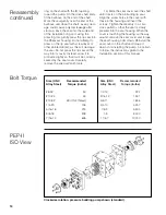
shown on the table on page 10. If the
flanges are not supplied by Zenith, make
certain that their mating faces are flat,
with no pilots that protrude into the pump.
Check that the pump rotates freely by
turning the shaft with your hand.
5) The pump drive shaft should be
connected to the motor drive assembly
with a flexible coupling, a double universal
joint shaft or an appropriate Zenith SJMC
coupling. Side loading on the pump shaft
is to be avoided at all costs.
6) If water is used for sealing, connect
either 1/8-27 or 1/4-18 NPT fittings to the
Rheoseal and turn on the water. Be sure
to avoid excessive cooling, or damage to
the pump may occur.
7) Turn on the pump heaters. A 250° F
temperature rise per hour is recommended
for cold starts. No attempt should be
made to start the pump until the entire
pump is at operating temperature.
Cold
starts are the most common cause of
pump failure.
On start-up, a small amount of molten
polymer should be introduced into the
pump by slowly rotating (less than 5 rpm)
the pump by hand to ensure that the
pump is free turning and well lubricated.
With sufficient inlet pressure, the pump
can then be started at a very slow speed,
with discharge pressure low enough to
maintain low loading. When operating
satisfactorily, the pump and system may
now be gradually brought up to normal
process speeds and pressures.


