
Disassembly
continued
8
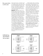
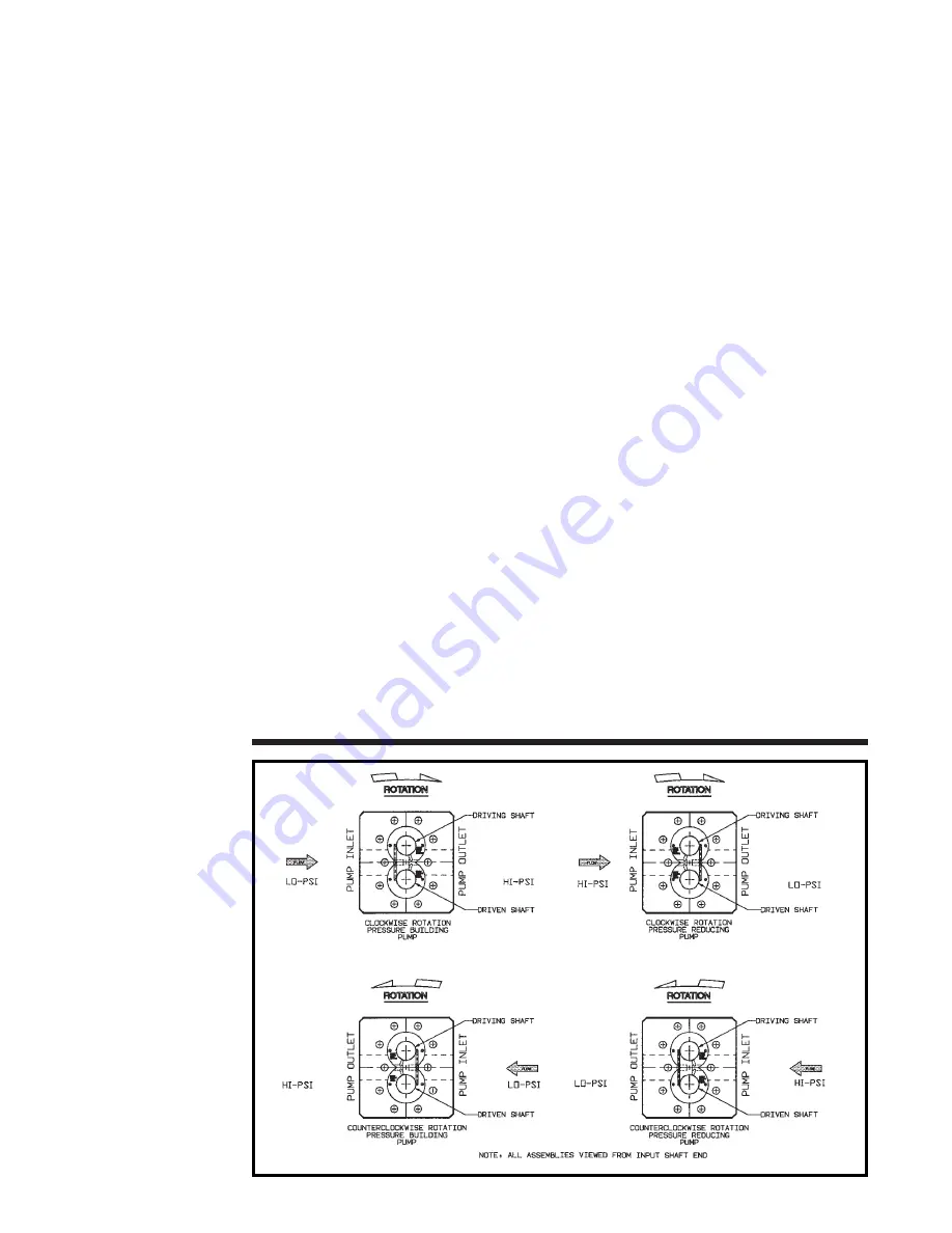
D-Bearing
Orientation
Schematic
plate and set aside in a safe place to pre-
vent damage. At this point, make certain
to note the orientation of the groove on the
rear of each bearing with respect to the
inlet port. They MUST be reassembled in
the same way as disassembled; that is,
they must point toward the inlet port, or
severe pump damage may result when
the pump is started.
WARNING:
(Read before steps 7 & 8)
Extreme caution must be exercised when
removing the gear shafts and bearing. For
the 40 cc/rev and above capacity pumps,
which have two (2) tapped holes in the D-
bearing faces, an optional disassembly
method is possible. If the gear shaft and
two D-bearings will not slide out as a
complete assembly after tapping with a
soft-faced hammer, it is recommended
that a gear puller tool be used to extract
the individual D-bearings from
each
side
of the gear shafts. If these still exhibit
force, soaking in a lubricating (penetrat-
ing) oil will help the disassembly.
For 20 cc/rev and smaller capa-
cities, there are no tapped holes in the
D-bearing faces to be utilized. The gear
shaft and D-bearings must be removed
as a complete assembly. Again, soaking
the parts in lubricating (penetrating) oil
or other non-damaging solution will help
ease the disassembly.
Do not force
the
parts out one side with a hammer or
arbor press.
7) Slide the gear shafts and bearings
out of the center plate. They will not come
out separately as the gear teeth will not
clear the bearings. Take extreme care not
to nick or ding the gear teeth or the edges
of the bearings. If they will not slide out
easily, use a hammer with a plastic or soft
brass head to gently tap them out. DO
NOT use a steel-headed hammer.
Alternate taps on the shafts until the parts
slide clear. Separate the two shaft/bearing
assemblies, taking care not to lose the
keys in the 10 cc/rev and smaller pumps.
There are no keys in the 20 cc/rev and
larger pumps.
8) Slide the bearings from the shafts,
again taking extreme care not to damage
the gear teeth, bearing edges or the
shafts. If the bearings will not slide easily
from the shaft (due to residual polymer),
use a plastic or soft brass-headed ham-
mer and a soft drift (NOT steel) to gently
tap the bearings free. Do not pry them off
with a screwdriver or other tool as this
may damage the gear teeth. Identify
which shaft the bearings came from, and
set them aside in a safe place.
9) On the 3 cc/rev and smaller, slide
the gears from their shafts and remove
the keys from the shaft.


