Reassembly
9
These instructions should be thoroughly
read and understood before starting
reassembly.
General instructions that should be
observed to ensure correct reassembly
of the pump are as follows:
• Using a solvent such as
trichloroethane or chloroethene Nu,
clean all parts that are to be used in the
reassembled pump.
WARNING
: Use extreme care when using
any solvent. Prolonged contact with the
liquid or inhalation of the vapor can cause
serious health problems.
• During and between each of the
assembly steps,
manually turn the
metering gears to ensure that they are
free turning.
If binding occurs at any time
during assembly,
determine
the cause
and
correct it before
proceeding further.
A tiny nick, burr or foreign particle can
extensively damage a valuable part if
allowed to remain. Never use excessive
force in assembling or turning a pump. If
properly aligned, the pieces will fit easily
into the plate, and the drive shaft will turn
freely.
All seals, O-rings and fasteners
must be replaced with new parts prior
to assembly.
• Use a soft-jawed vise to hold the
pump during reassembly.
• Before installing screws, lubricate
their threads with DAG Dispersion 154,
Felpro C-100, or similar heat-resistant
lubricant, and torque to prescribed values
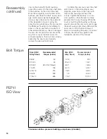
as shown on the table on page 10.
1) On 3.0 cc/rev and smaller pumps,
place a gear key on each shaft and slide
each gear onto its shaft, engaging the key.
2) Slide the gear shafts into the center
plate, taking care not to damage the gear
teeth. On 3.0 cc/rev and smaller pumps,
note that each shaft has a larger diameter
end. These larger ends must be on oppo-
site sides of the pump for the bearing
grooves to align properly.
3) Gently slide the gear shafts so that
the rear ends of the shafts protrude from
the rear of the center plate. On the 3.0
cc/rev and smaller pumps, take care not
to slide the shafts out of the gears and
allow the keys to drop out of the shafts.
4) Slide a bearing onto the drive shaft,
taking special care to select a bearing
with the proper groove configuration (and
with the proper ID on the 3.0 cc/rev and
smaller pumps). Slide the matching bear-
ing onto the driven shaft, taking care to
select a bearing with the proper groove
configuration. Set the flats on the circum-
ference of the bearings against each
other, and gently slide the bearings and
shafts into the center plate. Slide them far
enough through the center plate to allow
the drive shaft to protrude out on the front
side and allow the front bearings to be
installed. See D-bearing orientation
schematic on page 8.
5) Install the front bearings in the
same manner as the rear bearings, and
slide the bearings and shafts back into
the center plate so that the gears are
roughly in the center of the center plate.
6) For the 20 cc/rev and smaller
pumps, the bearings should be allowed to
protrude very slightly above the face of
the center plate before the cover plates
are installed. This will allow the bearings
to fit flush against the cover plates as
there are no bearing screws on these
smaller pumps. For 20 cc/rev and smaller
pumps, insert the bearing locating keys
on each side.
7) At this point make certain again
that there is no foreign matter on the faces
of the cover plates or on the faces of the
center plate. An accidental smudge of
thread lubricant can cause the small
pumps to bind.
8) Place the front cover plate on the
pump (and center on pump), checking
one more time that the configuration of the
bearing grooves is correctly oriented for
the inlet and discharge ports of the pump.
Insert the lubricated cover plate screws
into the pump and tighten them finger
tight only. Repeat for the rear cover plate.
9) On the 40 cc/rev and larger pumps,
insert the bearing retainer screws and
tighten them finger tight at this time.
10 Torque down the cover plate
screws in a crisscross pattern, taking
them first to 1/4 the recommended torque
value, then to 1/2, to 3/4 and finally to
their full recommended torque value.
11) Torque down the bearing retainer
screws in the same manner as the cover
plate screws. (Install C-Rings if applicable.)
12) Fit the Rheoseal seal housing to
the shaft. Loosely install but do not torque
down the seal housing screws, as this will
allow the lip seal to properly center the
housing.
13) Install the lip seals, using the
special Zenith installation tools as follows
to prevent damaging the seal. Install the
lip seals with the open face toward the
body of the pump. Slide the installation


