- 3-4 -
2. SYSTEM/KEY CIRCUIT
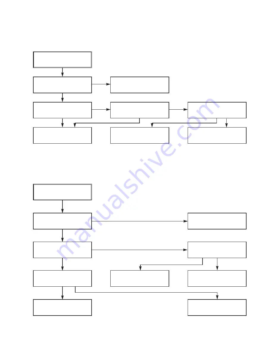
(1) AUTO STOP
(2) The unstable loading of a Cassette tape
Auto Stop
Does the SW25 waveform
appear at the IC501
Pin105?
Do the T-UP Reel Pulses
appear at the IC501 Pin49?
Is 12V applied to the
PMC01 Pin8?
Check the Drum Motor
signal.
Does 5.2V appear at the
RS501?
Check the Power Circuit.
Check the Power.
Is 5.3V applied to the
R544 ?
Refer to SMPS 5.3VA
troubleshooting.
Check the IC501
Pins68, 69, 70, 71.
Do T/UP Reel Pulses
appear at the Q514
Base terminal ?
Replace the T/UP Reel
Sensor (RS501).
Check the CST SW and
the peripheral circuitry.
Replace the IC501.
The unstable loading of a
Cassette tape
Does the H signal appear
at the IC501 Pin30 during
inserting the CST ?
Does the L signal appear
at the IC501 Pin72 during
inserting the CST?
Check the Deck
Mechanism.
Caution :
Auto stop can occur because Grease or Oil is dried up
YES
YES
YES
NO
YES
YES
YES
YES
NO
NO
NO
NO
NO
NO
NO
YES
YES
YES
Summary of Contents for XBS341 Series
Page 1: ...SERVICE MANUAL MODELS XBS341...
Page 10: ...2 1 SECTION 2 AUDIO PART...
Page 12: ...3 2 VCR ELECTRICAL TROULBESHOOTING...
Page 13: ...3 3...
Page 27: ...SECTION 4 MECHANSIM OF VCR PART...
Page 39: ...4 12...
Page 41: ...4 14...
Page 51: ...4 24...
Page 58: ...5 1 DVD ELECTRICAL TROUBLESHOOTING 1 Test debug flow SECTION 5 DVD PART...
Page 59: ...5 2...
Page 60: ...5 3...
Page 61: ...5 4...
Page 62: ...5 5...
Page 63: ...5 6...
Page 67: ...5 10 2 Tray close waveform 3 Tray open waveform...
Page 69: ...5 12 6 LASER POWER CONTROL RELATED SIGNAL NO DISC CONDITION 7 DISC TYPE JUDGEMENT WAVEFORM...
Page 70: ...5 13...
Page 71: ...5 14 8 FOCUS ON WAVEFORM...
Page 72: ...5 15 9 SPINDLE CONTROL WAVEFORM NO DISC CONDITION...
Page 73: ...5 16 10 TRACKING CONTROL RELATED SIGNAL System checking...
Page 74: ...5 17 11 RF WAVEFORM 12 MT1379 AUDIO OPTICAL AND COAXIAL OUTPUT ASPDIF...
Page 75: ...5 18 13 MT1379 VIDEO OUTPUT WAVEFORM 1 Full colorbar signal CVBS 2 Y...
Page 76: ...5 19 3 C 14 AUDIO OUTPUT FORM AUDIO DAC 1 Audio related Signal...
Page 77: ...5 20 MEMO...
Page 80: ...2 2 2 3 BLOCK DIAGRAM...
Page 81: ...2 4 2 5 AUDIO SHEMATIC DIAGRAMS U COM SCHEMATIC DIAGRAM...
Page 82: ...2 6 2 7 FUNCTION POWER SCHEMATIC DIAGRAM...
Page 83: ...2 8 2 9 MAIN AMP SCHEMATIC DIAGRAM...
Page 84: ...2 10 2 11 WIRING DIAGRAM...
Page 86: ...2 14 2 15 PRINTED CIRCUIT DIAGRAM MAINAMP FRONT P C BOARD SOLDER SIDE...
Page 87: ...2 16 2 17 MAINAMP FRONT P C BOARD COMPONENT SIDE...
Page 88: ...2 18 2 19 FUNCTION POWER P C BOARD SOLDER SIDE...
Page 89: ...2 20 2 21 FUNCTION POWER P C BOARD COMPONENT SIDE...
Page 90: ...3 17 3 18 VCR SHEMATIC DIAGRAMS SYSTEM SCHEMATIC DIAGRAM...
Page 91: ...3 19 3 20 A AUDIO V VIDEO SCHEMATIC DIAGRAM...
Page 93: ...3 23 3 24 HIFI TUNER SCHEMATIC DIAGRAM...
Page 94: ...3 25 3 26 A V JACK SCART SCHEMATIC DIAGRAM...
Page 96: ...3 29 3 30 PRINTED CIRCUIT DIAGRAMS TUNER P C BOARD...
Page 97: ...3 31 3 32 VCR P C BOARD...
Page 98: ...3 33 3 34 VCR P C BOARD...
Page 99: ...5 22 5 21 DVD PART SCHEMATIC DIAGRAMS MPEG SCHEMATIC DIAGRAM...
Page 100: ...5 23 5 24 SERVO SCHEMATIC DIAGRAM...
Page 101: ...5 25 5 26 AUDIO SCHEMATIC DIAGRAM...
Page 102: ...5 27 5 28 INTERFACE SCHEMATIC DIAGRAM...
Page 103: ...5 29 5 30 VOLTAGE SHEET IC TR...
Page 104: ...5 31 5 32 PRINTED CIRCUIT DIAGRAM DVD P C BOARD SOLDER SIDE...
Page 105: ...5 33 5 34 DVD P C BOARD COMPONENT SIDE...
Page 107: ...MEMO MEMO...
Page 109: ...MEMO MEMO...
Page 115: ......


