4-14
DECK MECHANISM ADJUSTMENT
Purpose: To insure smooth transport of the tape during each mode of operation.
If the tape transport is abnormal, then check the torque as indicated by the chart below.
2. Preparation for Adjustment (To set the
Deck Mechanism of the loading state
without inserting a cassette tape).
1) Unplug the power cord from the AC outlet.
2) Disassemble the Top Cover and Plate Assembly Top.
3) Plug the power cord into the AC outlet.
4) Turn the power S/W on and push the Lever Stopper of
the Holder Assembly CST to the back for loading the
cassette without tape.
Cover the holes of the End Sensors at the both sides of
the Chassis to prevent a light leak.
Then the Deck Mechanism drives to the Stop Mode.
In this case, the Deck Mechanism can accept inputs of
each mode, however the Rewind and Review operation
can not be performed for more than a few seconds
because the Take-up Reel Table is in the Stop State
and can not be detected the Reel Pulses.
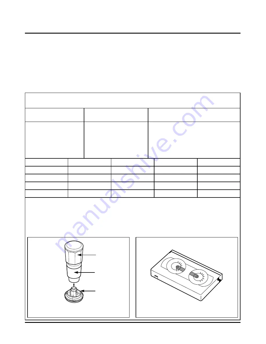
3. Checking Torque
NOTE:
The values are measured by using a Torque Gauge and
Torque Gauge Adaptor with the Torque Gauge affixed.
NOTE:
The torque reading to measure occurs when the tape
abruptly changes direction from Fast Forward to Rewind
Mode, when quick braking is applied to both Reels.
SRK
VIDEO
CASSETTE
TORQUE
METER
VHT-303
S
R
K
-
V
H T
- S
SR
K - V H T - T
300
250
200
150
50
0
300
250
200
150
50
0
100
Test Equipment/ Fixture
• Torque Gauge(600g/cm ATG)
• Torque Gauge Adaptor
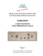
• Cassette Torque Meter
SRK-VHT-303
Checking Method
• Perform each Deck Mechanism mode without
inserting a cassette tape(Refer to above No.2
Preparation for Adjustment).
• Read the measurement of the Take-up or Supply
Reels on the Cassette Torque Meter(Fig. C-3-2).
• Attach the Torque Gauge Adaptor to the Torque
Gauge and then read the value of it(Fig. C-3-1).
Fig. C-3-2
Fig. C-3-1
Torque Gauge
Torque Gauge
Adaptor
Reel Table
Item
Fast Forward Torque
Rewind Torque
Play Take-Up Torque
Review Torque
Mode
Fast Forward
Rewind
Play
Review
Test Equipment
Cassette Torque Gauge
Cassette Torque Gauge
Cassette Torque Meter
Cassette Torque Meter
Measurement Reel
Take-Up Reel
Supply Reel
Take-Up Reel
Supply Reel
Measurement Values
More than 400g/cm
More than 400g/cm
40~100g/cm
120~210g/cm
Test Conditions
(Mechanism Condition)
• Play (FF) or Review (REW) Mode
• Cassette Torque Meter (SRK-VHT-303)
• Torque Gauge (600g.cm ATG)
Summary of Contents for XBS344 Series
Page 2: ......
Page 10: ...2 3 951 954 960 961 953 957 959 955 956 963 A90 2 Woofer Speaker Section DTE 5105WE...
Page 11: ...2 4 850 852 851A 851 853 854 857 858 A80 3 Speaker Section DTE 550TE...
Page 38: ...3 34 3 35 2 POWER SMPS CIRCUIT DIAGRAM 2 SR13601A R171 4 7K...
Page 39: ...3 36 3 37 3 JACK TUNER CIRCUIT DIAGRAM 03 08 15 SR13605A...
Page 43: ...3 44 3 45 7 KEY CIRCUIT DIAGRAM SR13610A...
Page 46: ...3 50 3 51 PRINTED CIRCUIT DIAGRAMS 1 MAIN P C BOARD LOCATION GUIDE...
Page 47: ...3 52 3 53 2 TUNER P C BOARD LOCATION GUIDE 3 POWER P C BOARD...
Page 48: ...3 54 3 55 4 KEY 1 LEFT P C BOARD LOCATION GUIDE 5 KEY 2 RIGHT P C BOARD LOCATION GUIDE...
Page 49: ......
Page 69: ...3 75 3 C IC507 PIN 26 FIG 12 3 2 Y IC507 PIN 21 FIG 12 2...
Page 77: ......
Page 79: ...CD DVD LD will not on SR13608A VZ DV51V SANYO 3 85 3 86 2 RF SERVO CIRCUIT DIAGRAM...
Page 80: ...VZ DV51V SANYO TUNER_L TUNER_R 3 87 3 88 3 AUDIO _COM CIRCUIT DIAGRAM DVD AMP...
Page 81: ...VZ DV51V SANYO FRONT_R FRONT_L REAR_R REAR_L 3 89 3 90 4 DIGITAL AMP CIRCUIT DIAGRAM DVD AMP...
Page 82: ...5 PWM CODEIC CIRCUIT DIAGRAM DVD AMP VZ DV51V SANYO 12 288MHz R R L L R L OPTICAL_IN 3 91 3 92...
Page 83: ...6 INTERFACE CIRCUIT DIAGRAM DVD AMP VZ DV51V SANYO 3 93 3 94...
Page 86: ...LOCATION GUIDE LOCATION GUIDE 3 99 3 100 PRINTED CIRCUIT DIAGRAMS 1 DVD AMP P C BOARD...
Page 87: ......
Page 119: ...MEMO...
Page 125: ......
Page 127: ......
Page 159: ......


