SCSI ID Jumper Settings
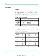
Terminal J6 determines the SCSI ID and whether the spindle
synchronization is enabled and whether an external LED is used.
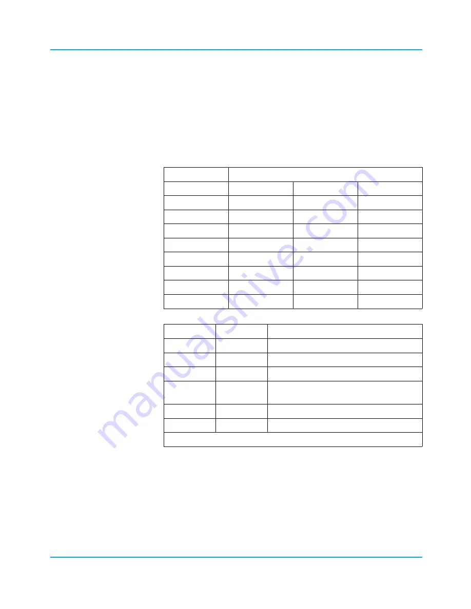
The following tables show the SCSI ID and jumper settings.
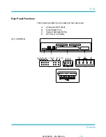
Refer to the illustration at the end of this section for the location
of the J6 terminal on the board.
J6 TERMINAL PINS
SCSI ID
A2
A1
A0
ID 0
OUT
OUT
OUT
ID 1
OUT
OUT
IN
ID 2
OUT
IN
OUT
ID 3
OUT
IN
IN
ID 4
IN
OUT
OUT
ID 5
IN
OUT
IN
ID 6
IN
IN
OUT
ID 7
IN
IN
IN
J6 PIN NAME DEFAULT
DESCRIPTION
A2
*
Drive ID Bit 2
A1
*
Drive ID Bit 1
A0
*
Drive ID Bit 0
SSP
OUT
Sync Spindle signal () cable
connection
LED
OUT
Remote LED cable connection
RES
OUT
Reserved
* Refer to the drive bay assignments at the beginning of this chapter.
04/APRIL/93 – 595-5484-UU
175
175
D-7
Devices


