background image

18


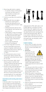
 Mounting with plastic adapter:


 Insert the 2 halves of the plastic 

connector into the sensor’s 

three notches (crimps) and 

press them together.


 Use the mounting aid as position-

ing aid.


 Mounting with brass adaptor:


 Slide brass screwing with 

loosely mounted groove pin 

onto temperature sensor in right 

position


 Slide temperature sensor into 

mounting aid until mechanical 

stop (28 mm)


 Check again, if brass screwing is 

in right position (the groove pin 

must be pressed in the upper 

groove which is in the closest 

position to the temperature 

sensor cable)


Press in groove pin flush


Remove mounting aid


 Insert the temperature sensor 

into the installation point and 

screw it in tightly until the dead 

stop of the seal on the 12-point is 

reached (mounting torque 


3-5 Nm).


 The temperature sensor instal-

lation point which is optionally 

integrated in the flow sensor must 

be secured.


 Secure the sensor after instal

-

lation against unauthorised 

removal with appropriate sealing 

(included in accessories kit)!


 At the versions with temperature 

sensor type TS-45-5 (see type 

plate at the sensor cable) both 

sensors must be always immersed 

directly in contact with the heat 

conducting fluid. The installation 

in sensor pockets is not allowed.

Installation with existing immersion 

sleeves

In Germany the C5 can be put into 

use in connection with existing im-

mersion sleeves in accordance with 

the article “Putting into use of MID 

homologated temperature sensors” 

released in the PTB notifications 119 

(2009), Edition 4. Based on current 

information, the regulation has a pe-

riod of validity until 30.10.2026. For 

the identification and marking of the 

usable existing immersion sleeves 

in connection with the C5 meter, an 

identification and marking set can be 

delivered from our company (order 

number 137382).

Commissioning


 Open valves carefully. Vent the 

system. Avoid sudden pressure 

shocks. Check installation for 

leakage.


Attention! 


For zelsius C5 with 

LoRa interface, we 

recommend at first 

to do the onboarding of the device 

on your respective IoT platform by 

putting in the key information 

belonging to the device (DevEUI, 

JoinEUI and AppKey) before 

activating the device as described 

below!


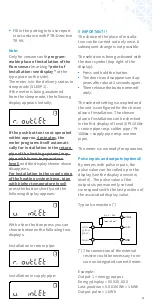
 If the sleep mode of the counter is 

enabled (Display: SLEEP 1), then 

it must be deactivated by longer 

pressing the button (>5s).


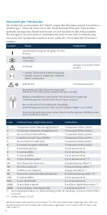
 While the system is operating, 

check whether the volume display 

advances and the temperatures 

displayed correspond with the ac-

tual temperatures (see the display 

overview).


 Wait for the temperature display 

to be updated.


 Secure meter with the enclosed 

sealing material against unau-

thorised removal.

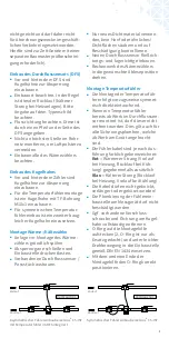
Mounting example

Summary of Contents for zelsius C5 -ISF

Page 1: ...h M Bus wM Bus LoRaWAN and 3 inputs outputs qp 0 6 1 5 2 5 m h GB PDF Download Notice d installation Istruzioni per il montaggio Notice d installation et d utilisation 26 Compteur lectronique d nergie...

Page 2: ...des Durchflusssensors DFS 5 Einbau des Kugelhahns 5 Montage W rme K ltez hler 5 Montage Temperaturf hler 5 Einbau in Bestandstauchh lsen 6 Inbetriebnahme 6 Impulsein und ausg nge optional 7 M Bus opt...

Page 3: ...Mindestdruck zur Vermeidung von Kavitation bar 0 3 Nenndruck Spitzendruck PS PN 16 16 IP Schutzklasse 54 65 f r K ltez hlung und kombinier te W rme K ltez hlung Einbaulage horizontal horizontal um 90...

Page 4: ...erlegt werden Abstand mind 0 2 m Pflegehinweise Kunststoffoberfl chen nur mit feuch tem Tuch reinigen Keine scheuern den oder aggressiven Reinigungsmit tel einsetzen Das Ger t ist ber die Einsatzdauer...

Page 5: ...s ubern und auf Besch digung kontrollieren Neuen Durchflusssensor flie rich tungs und lagerichtig einbauen Rechenwerk des W rmez hlers in die gew nschte Ableseposition drehen Montage Temperaturf hler...

Page 6: ...Artikel Einsatz MID konformer Temperaturf hler f r W rmez hler in Bestandstauchh lsen ver ffent licht in den PTB Mitteilungen 119 2009 Heft 4 eingesetzt werden Die Regelung hat nach aktuellem Stand d...

Page 7: ...s zugeh rigen Anzeigenwerts Typische Beschaltung Der Anschlu eines externen Widerstandes kann notwendig sein um die Strombegrenzung zu gew hrleisten Inbetriebnahmeprotokoll gem PTB Richtlinie TR K9 au...

Page 8: ...s zelsius Energiez hler die ber eine integrierte Funkschnittstelle mit Antenne verf gen sind zur besseren Erkennbarkeit auf der Oberschale je nach Ausf hrung mit folgenden Symbolen gekennzeichnet wM B...

Page 9: ...e f r Leistung und Durchfluss im Sendeintervall Daten wireless M Bus LoRaWAN Frequenzband 868 MHz 868 MHz Funkprotokoll wireless M Bus EN 13757 4 und gem Open Metering Standard OMS unterschiedliche Pr...

Page 10: ...ag bis heute K lteenergie vom letzten Stichtag bis heute Aktueller Monatsverbrauch W rmeenergie Aktueller Monatsverbrauch K lteenergie Aktuelles Monatsvolumen Maximaler Durchfluss Maximaler Monats Dur...

Page 11: ...r verschiedene Mischungsverh ltnisse durchlaufen E 20 E 25 E 30 E 35 E 40 E 45 E 50 P 20 P 25 P 30 P 35 P 40 P 45 P 50 E 0 E Ethylenglykol P Propylenglykol E 0 Wasser ohne Glykol Zusatz Bei Erreichen...

Page 12: ...ler pr fen 4 Unterbrechung R cklauff hler Temperaturf hler pr fen 5 Kurzschluss Vorlauff hler Temperaturf hler pr fen 6 Unterbrechung Vorlauff hler Temperaturf hler pr fen 7 Batteriespannung Ger t aus...

Page 13: ...der Nut zungsdauer wieder mitnehmen und fachgerecht entsorgen Sofern dies bez glich keine andere vertragliche Regelung getroffen wurde k nnen alternativ die Altger te und Zubeh r auch bei unserer Betr...

Page 14: ...FS 17 Installation of the ball valve 17 Mounting heat cooling energy meter 17 Installation of the temperature sensors 17 Installation with existing immersion sleeves 18 Commissioning 18 Pulse inputs...

Page 15: ...o avoid cavitation bar 0 3 Nominal pressure peak pressure PS PN 16 16 IP protection class 54 65 for heating and cooling energy metering Installation position horizontal horizontal tipped through 90 ve...

Page 16: ...ce 0 2 m Care instructions Clean plastic surfaces with a damp cloth only Do not use any scouring or aggressive cleaning agents The device is maintenance free during the service life Repairs may only b...

Page 17: ...puter to desired reading position Installation of the temperature sensors The installation of the tempera ture sensors should be prefer ably symmetrical and as direct installation Do not remove the te...

Page 18: ...pockets is not allowed Installation with existing immersion sleeves In Germany the C5 can be put into use in connection with existing im mersion sleeves in accordance with the article Putting into use...

Page 19: ...r could be necessary to en sure an integrated current limiter Example Output 1 energy output Energy display XXXXX XXX Last position 0 001 MWh 1 kWh Output pulse 1 kWh U 3 30 V Imax 20 mA GND Pulse V O...

Page 20: ...urn to the main display Radio optional General information zelsius energy meters which have an integrated radio interface with an antenna are marked for better visibil ity on the upper cover with one...

Page 21: ...ng transmitting interval Data wireless M Bus LoRaWAN Frequency 868 MHz 868 MHz Radio protocol Wireless M Bus EN 13757 4 and according to the Open Metering Standard OMS different radio telegram content...

Page 22: ...due date to now Cooling energy difference from last due date to now Heat energy difference from 1 of this month to now Cooling energy difference from 1 of this month to now Volume difference from 1 o...

Page 23: ...nds until letter E flashes With each short press on the button the following loop for different mixing ratios runs E 20 E 25 E 30 E 35 E 40 E 45 E 50 P 20 P 25 P 30 P 35 P 40 P 45 P 50 E 0 E ethylene...

Page 24: ...ck sensors 5 Short circuit supply sensor Check sensors 6 Interruption supply sensor Check sensors 7 Battery voltage Exchange device 8 Hardware error Exchange device 9 Hardware error Exchange device 10...

Page 25: ...posal Alternatively a waste disposal via ZENNER is possible Your local or municipal authority or the local waste disposal company can give you information relating the collec tion points for your use...

Page 26: ...s vannes 29 Montage du compteur d nergie thermique frigorifique 29 Connection des sondes de temp rature 29 Indications relatives au montage des doigts de gants existants 30 Mise en service 30 Entr es...

Page 27: ...C 10 q 90 Pression minimale pour viter la cavitation bar 0 3 Pression nominale Pression maximale PS PN 16 16 Indice de protection 54 65 pour la mesure combin e de frigorie et d nergie thermique de fr...

Page 28: ...conduisant le courant du r seau lectrique 230 V distance minimale 0 2 m Conseils d entretien Nettoyez les surfaces plastiques uniquement avec un chiffon humide N utilisez pas de d tergents abrasifs ou...

Page 29: ...D monter l ancien mesureur de volume adaptateur Employez uniquement des mat riaux d tanch it neufs et sans d faut pas de chanvre ou simi laire Nettoyez les surfaces d tan ch it et assurez vous qu elle...

Page 30: ...rni Pour des versions avec type de sonde de temp rature TS 45 5 voir plaque signal tique sur le c ble les deux sondes doivent toujours tre mont es dans l agent caloporteur Le montage dans un doigt de...

Page 31: ...t typique Le raccordement d une r sistance externe peut s av rer n cessaire pour garantir la limitation du courant U 3 30 V Imax 20 mA GND Pulse V Out blanc jaune vert marron impulsion Attendez pour l...

Page 32: ...Radio en option G n ralit s Les compteurs d nergie zelsius qui disposent d une interface radio int gr e avec l antenne sont marqu sur le capot sup rieur par le symbole suivant pour une meilleure visib...

Page 33: ...ans l intervalle de transmission Sp cifications wireless M Bus LoRaWAN Fr quence 868 MHz 868 MHz Protocole radio wireless M Bus EN 13757 4 et conforme Open Metering Stan dard OMS diff rents protocolle...

Page 34: ...Test segment Date rep re Energie la date rep re Energie frigorifique la date rep re Volume D bit Temp rature aller Temp rature retour Diff rence de temp rature Puissance instantan e Energie thermique...

Page 35: ...ur e sur la touche respective les diff rentes proportions de m langes sont parcourues en boucle E 20 E 25 E 30 E 35 E 40 E 45 E 50 P 20 P 25 P 30 P 35 P 40 P 45 P 50 E 0 E Ethyl neglycol P Propyl negl...

Page 36: ...mp rature 5 Court circuit sonde aller V rifier sondes de temp rature 6 Interruption sonde retour V rifier sondes de temp rature 7 Tension pile Remplacer l appareil 8 Erreur du mat riel Remplacer l app...

Page 37: ...R peut galement liminer votre appareil usag Les points de reprise de vos appareils usag s sont disponibles par exemple la mairie locale aupr s des d chetteries locales Zenner assure dans tous les cas...

Page 38: ...stallazione della valvola a sfera 41 Installazione del contatore di calore raffrescamento 41 Installazione delle sonde di temperatura 41 Installazione con manicotti ad immersione esistenti 42 Messa in...

Page 39: ...la cavitazione bar 0 3 Pressione nominale pressione di picco PS PN 16 16 Classe di protezione IP 54 65 per la misurazione dell energia di riscaldamento e raffrescamento Posizione di installazione oriz...

Page 40: ...operazione di manutenzione durante gli anni di validit della taratura Le riparazioni possono essere eseguite solo dal produttore o da partner di assistenza autorizzati Manuale di installazione Indicaz...

Page 41: ...ntrollarne l usura Montare la volumetrica nuova in base alla direzione di flusso e alla posizione Girare la parte elettronica del con tatore nella posizione di lettura desiderata Installazione delle s...

Page 42: ...onde devono essere sempre installate direttamente nel fluido NON consentita l installa zione in pozzetti Installazione con manicotti ad im mersione esistenti Secondo l articolo Installazione della son...

Page 43: ...garantire una limitazione di corrente U 3 30 V Imax 20 mA GND Pulse V Out bianco giallo verde mar rone impulso Attendere l aggiornamento della temperatura sul display Al termine della messa in funzion...

Page 44: ...dispongono di un interfaccia radio integrata con un antenna sono con trassegnati per una migliore visibilit sul coperchio superiore con uno dei seguenti simboli wM Bus Esempio Uscita 1 uscita energia...

Page 45: ...ri medi di portata e potenza nell intervallo di trasmissione Dati wireless M Bus LoRaWAN Frequenza 868 MHz 868 MHz Protocollo radio wireless M Bus EN 13757 4 secondo Open Metering Stan dard OMS Possib...

Page 46: ...o fino ad oggi Energia di raffrescamento dall ultimo giorno fisso d azzeramento fino ad oggi Calore differenza dal 1 di questo mese ad oggi Raffrescamento differenza dal 1 di questo mese ad oggi Volum...

Page 47: ...ne del pulsante comparir il seguente elenco di numeri per diverse concentrazioni di miscele glicolate E 20 E 25 E 30 E 35 E 40 E 45 E 50 P 20 P 25 P 30 P 35 P 40 P 45 P 50 E 0 E glicole etilenico P gl...

Page 48: ...o circuito sonda del ritorno Controllo delle sonde di temperatura 5 5 Controllo delle sonde di temperatura 6 Interruzione sonda della mandata Controllo delle sonde di temperatura 7 Voltaggio difforme...

Page 49: ...tituzione o la loro durata utile e che li smaltiscano in maniera corretta Per ulteriori informazioni potete contattare la ns sede al seguente numero telefonico 051 198 733 80 ZENNER assicurer sempre d...

Page 50: ...Notice...

Page 51: ......
Page 52: ...Irrt mer und Druckfehler bernehmen wir keine Haftung ZRI_SAP155769_191028 ZENNER International GmbH Co KG R merstadt 6 66121 Saarbr cken Germany Telefon 49 681 99 676 30 Telefax 49 681 99 676 3100 E...

Reviews: