background image


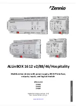
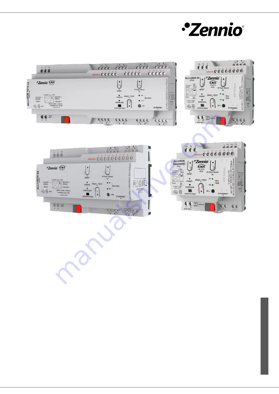
ALLinBOX 1612 v2/88/46/Hospitality 


Multifunction device with power supply, KNX-IP Interface, 

outputs, inputs, and logical module 


ZPR1612V2 

ZPR88 
ZPR46 

ZPRHP 

U

S

E

R

 M

A

N

U

A

L


Application program version: [1.5]  

User manual edition: [1.5]_a 


www.zennio.com


Summary of Contents for ALLinBOX 1612 v2

Page 1: ...46 Hospitality Multifunction device with power supply KNX IP Interface outputs inputs and logical module ZPR1612V2 ZPR88 ZPR46 ZPRHP USER MANUAL Application program version 1 5 User manual edition 1...

Page 2: ...Reset power supply 12 2 Configuration 13 2 1 KNX to IP Interface 13 2 2 Programmer 14 2 2 1 Parallel Downloads 15 2 3 Additional Individual Addresses Tunneling Addresses 17 2 4 General 18 2 5 Inputs...

Page 3: ...DOCUMENT UPDATES Version Changes Page s 1 5 _a New devices ALLinBOX Hospitality Changes in the application program Date time synchronisation via NTP Optimisation of the shutters standard thermostat ho...

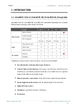
Page 4: ...emperature Probes 12 8 6 6 Binary Inputs 12 8 6 6 Motion Detectors 12 8 6 6 Thermostats Standard 4 4 4 Hospitality 4 4 4 2 In addition to these functions there are others common to all ALLinBOX 20 cus...

Page 5: ...rs for the power supply power and overload 1 power supply factory reset indicator 2 state indicators for the lines bus and Ethernet 1 IP factory reset indicator and 1 additional indicator for the prog...

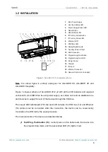
Page 6: ...hernet 18 cables must be connected After the connection the device can be conveniently mounted on the DIN rail by the usual procedure The main elements of the device are described below Test Prog Push...

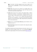
Page 7: ...ature probes etc One of the two cables of each element need to be connected to one of the slots labelled 1 to 12 1 to 8 1 to 6 while the other cable should be connected to the slot labelled as C Note...

Page 8: ...e integrator can set whether the output channels should switch to a particular state and whether the device should send certain objects to the bus after the power recovery Please consult the next sect...

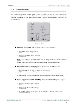
Page 9: ...F KNX line is not powered ON green KNX line is powered Note the update of the LED status can be delayed a few seconds after the trigger event e g after the disconnection of the main power supply Ether...

Page 10: ...ower output line Reduce the load on the bus and or the auxiliary power output lines until its total consumption does not exceed the maximum current specified Programming LED OFF normal operation ON re...

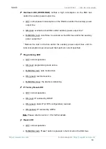
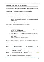
Page 11: ...nd long press is made on the IP Factory Reset button The device will adopt a static IP address If Use a static IP address has been chosen on the ETS configuration the device will have the configured I...

Page 12: ...TS configuration Green 1 6 HARD RESET POWER SUPPLY If Reset button is pressed a short circuit is made in the output power supply 29V The device will not restart and will not give power until the butto...

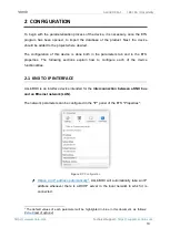
Page 13: ...erties The following sections explain how to configure each of the device functionalities 2 1 KNX TO IP INTERFACE ALLinBOX is an interface device intended for the interconnection between a KNX bus and...

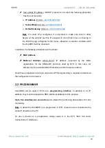
Page 14: ...on will be shown MAC Address Multicast Address 224 0 23 12 IP address reserved by the IANA organization for the KNXnet IP protocol used by ETS in this case for discovering the available KNX IP interfa...

Page 15: ...to first perform individual address download and then application download rather than a complete download complete download causes a device restart and therefore communication with ETS is lost and t...

Page 16: ...download physical addresses When performing this type of downloads the link device used by ETS is not the one configured for the line but the general one In Settings panel in Properties of the line t...

Page 17: ...address of the device itself Up to five simultaneous connections are possible which implies that up to five different individual addresses must be configured After the individual ALLinBOX address has...

Page 18: ...m this screen it is possible to activate deactivate all the required functionality Figure 8 General screen Inputs disabled enabled enables or disables the Inputs tab on the left menu See section 2 5 f...

Page 19: ...egrator activate two new communication objects Reset 0 and Reset 1 which will be sent to the KNX bus with values 0 and 1 respectively whenever the device begins operation for example after a bus power...

Page 20: ...abled enabled enables or disables the NTP tab in the tree on the left For more information see section 2 11 Note This parameter must be enabled in the device that will be clock master so that there is...

Page 21: ...nnio Motion Detector to connect a motion detector from Zennio 2 5 1 BINARY INPUT Please refer to the Binary Inputs user manual available under the ALLinBOX 1612 v2 88 46 Hospitality product section at...

Page 22: ...can be controlled Shutter channel which enables the control of the motion of one blind up to 8 4 2 blinds can be controlled Fan Coil modules to control fan coils fan and valves up to 2 1 13 modules ca...

Page 23: ...ion and ALLinBOX type Fan coil Numbe r pipes Valve type Output Action ALLinBOX 1612 v2 88 46 1 4 On Off B2 Cooling Valve C1 Heating Valve Three point B2 Opening Cooling Valve C1 Closing Cooling Valve...

Page 24: ...tputs screen The fan coil module is intended to operate the relay that open and close a water pipe valve one on off valve only and the relays that set the fan speed level The latter can be achieved th...

Page 25: ...ndently ALLinBOX Hospitality implements two Hospitality thermostats which can be enabled and configured independently The use of the Hospitality thermostat is only recommended for hotel rooms Please r...

Page 26: ...e bus it is up to the integrator the decision of what to send to the KNX bus in both cases a shutter order a thermostat setpoint or mode switch order a constant value a scene Only the trigger object a...

Page 27: ...ays be available in the project topology It will be sent to the bus with a value of 1 whenever there is at least one of the above state objects with such value Otherwise i e if none of them has a valu...

Page 28: ...an HVAC thermostat mode value configurable in Value Auto Comfort Standby Economy Building Protection whenever the general switch off takes off Note the above options are not mutually exclusive it is p...

Page 29: ...h The execution of each function can depend on a configurable condition which will be evaluated every time the function is triggered through specific parameterisable communication objects The result a...

Page 30: ...ill pending for that output channel module such temporisation will be interrupted and only the delay and the action of the new scene will be executed ETS PARAMETERISATION Prior to setting the scene ti...

Page 31: ...ame output appear in the configuration tab of the delays of that scene With this parameterisation the behaviour will be as follows the action and delay of the first scene parameterised with the same s...

Page 32: ...e to configure if the manual control will be available Moreover it is possible to enable a specific binary object for locking and unlocking the manual control in runtime Note Switching to the Test On...

Page 33: ...imes Note after leaving the Test On mode the status objects will recover the values they had prior to entering Test On As the device is never aware of the actual position of the shutter as the shutter...

Page 34: ...t when exiting this mode so that any change in the alarm status or blocking of the outputs while Test ON mode is active is taken into account when exiting this mode and is updated with the last status...

Page 35: ...nlock 1 Lock defines whether the manual control lock unlock should take place respectively upon the reception through the aforementioned object of values 0 and 1 or the opposite Initialization Unlocke...

Page 36: ...ding of 1 3 1 Bit I C W DPT_Enable 0 1 Lock Manual Control 0 Lock 1 Unlock 1 Bit I C W DPT_Enable 0 1 Lock Manual Control 0 Unlock 1 Lock 4 1 Bit C T DPT_Trigger 0 1 Heartbeat Object to Send 1 Sending...

Page 37: ...3 222 1 Bit O C R T DPT_UpDown 0 1 Cx Movement Direction Status 0 Upward 1 Downward 194 223 1 Bit I C W DPT_Switch 0 1 Cx Auto On Off 0 On 1 Off 1 Bit I C W DPT_Switch 0 1 Cx Auto On Off 0 Off 1 On 19...

Page 38: ...1 Automatic 420 1 Bit O C R T DPT_Enable 0 1 FCx Fan Manual Automatic Status 0 Automatic 1 Manual 1 Bit O C R T DPT_Enable 0 1 FCx Fan Manual Automatic Status 0 Manual 1 Automatic 421 1 Bit I C W U DP...

Page 39: ...ating Fan Continuous Control 0 100 1 Byte I C W U DPT_Scaling 0 100 FCx Heating Valve PI Control Continuous 0 100 436 1 Bit I C W U DPT_OpenClose 0 1 FCx Cooling Valve Control Variable 1 bit 0 Open Va...

Page 40: ...519 525 531 537 543 1 Bit I C W DPT_Enable 0 1 Ix Input Lock 0 Unlock 1 Lock 514 520 526 532 538 544 1 Bit C T DPT_Switch 0 1 Ix Short Press 0 Sending of 0 1 Bit C T DPT_Switch 0 1 Ix Short Press 1 Se...

Page 41: ...ing 0 100 Ix Short Press Constant Value Percentage 0 100 2 Bytes C T DPT_Value_2_Ucount 0 65535 Ix Short Press Constant Value Integer 0 65535 2 Bytes C T 9 xxx 671088 64 670433 28 Ix Short Press Const...

Page 42: ...p 1 Bit C T DPT_Switch 0 1 Ix Long Press Light On Sending of 1 On 1 Bit C T DPT_Switch 0 1 Ix Long Press Light Off Sending of 0 Off 1 Bit I C W T DPT_Switch 0 1 Ix Long Press Light On Off Switching 0...

Page 43: ...1 Motion Detected 593 622 651 680 709 738 1 Bit I C W DPT_Window_Door 0 1 Ix Presence Trigger Binary Value to Trigger the Presence Detection 594 623 652 681 710 739 1 Bit I C W DPT_Start 0 1 Ix Prese...

Page 44: ...946 950 954 958 1 Bit O C R T DPT_Alarm 0 1 Ix Probe Error 0 No Alarm 1 Alarm 983 984 985 986 987 988 989 990 991 992 993 994 995 996 997 998 999 1000 1001 1002 1003 1004 1005 1006 1007 1008 1009 101...

Page 45: ...1154 1155 1156 1157 1158 1159 1170 1171 1172 1173 1174 1175 1176 1177 1178 1179 1180 1181 1 Bit I C W DPT_Switch 0 1 MLx Status Object x Binary Status 1160 1182 1 Bit O C R T DPT_Switch 0 1 MLx Genera...

Page 46: ...ytes I C W T U DPT_Value_Temp 273 00 670433 28 HTx B User Setpoint Control 20 C 100 C 2 Bytes I C W T U DPT_Value_Tempd 671088 64 670433 28 HTx B User Setpoint Offset 15 C 15 C 1206 1274 1342 1410 1 B...

Page 47: ...etpoint Reset Time Hours 0 Disabled 1220 1288 1356 1424 1 Bit I O C R W DPT_Occupancy 0 1 HTx C Presence Detector Input 0 Not Occupied 1 Occupied 1221 1289 1357 1425 1 Bit I O C R W DPT_Enable 0 1 HTx...

Page 48: ...HTx D Thermostat Lock 0 Unlocked 1 Locked 1236 1304 1372 1440 2 Bytes I O C R W T U DPT_Value_Temp 273 00 670433 28 HTx D Comfort Lower Limit 20 C 100 C 1237 1305 1373 1441 2 Bytes I O C R W T U DPT_V...

Page 49: ...0 1258 1326 1394 1462 1 Bit O C R T DPT_Switch 0 1 HTx Heating PI State 0 PI Signal 0 1 PI Signal Greater than 0 1463 1 Byte I C W DPT_SceneControl 0 63 128 191 Thermostat Scene Input Scene Value 1464...

Page 50: ...f Status 0 Off 1 On 1486 1524 1562 1600 1 Bit I O C R W DPT_Switch 0 1 Tx Main System Cool 0 System 1 1 System 2 1487 1525 1563 1601 1 Bit I O C R W DPT_Switch 0 1 Tx Main System Heat 0 System 1 1 Sys...

Page 51: ...al 0 1 PI Signal Greater than 0 1616 3 Bytes O C R T DPT_Date 01 01 1990 31 12 2089 NTP Date Current Date 1617 3 Bytes O C R T DPT_TimeOfDay 00 00 00 23 59 59 NTP Time of Day Current Time 1618 8 Bytes...

Page 52: ...n and send us your inquiries about Zennio devices https support zennio com Zennio Avance y Tecnolog a S L C R o Jarama 132 Nave P 8 11 45007 Toledo Spain Tel 34 925 232 002 www zennio com info zennio...

Reviews: