background image


DALIBOX Interface 64/32


http://www.zennio.com


Technical Support:


http://support.zennio.com 


33 

2.5


GROUP N 

2.5.1


CONFIGURATION 

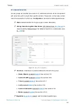
The general configuration for each group involves the following options: 


Group name

: name of up to twelve characters that will identify the group along 

the options of the device display. 


Dimming value during DALI bus failure

: sets the dimming level that will be 

adopted  by  the  ballasts  of  the  channel  if  communication  errors  take  place 

between  DALIBOX  Interface  64/32  and  the  ballasts,  which  may  be  due  to 

short-circuits

 or to a 

power supply failure

Note

during the absence of the KNX bus, on the contrary, DALIBOX Interface 

64/32  will  keep  powering  the  DALI  groups  (even  if  the  external  power  LED 

indicator remains off), thus making the ballasts remain in the last dimming level. 

Note that timed actions will be stopped and will not be resumed when the KNX 

bus voltage is recovered


Functions

: configuring a set of custom functions per group is possible: 


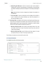
Status objects

: allows enabling or disabling the status objects associated 

to each channel (On/Off and dimming value). See section 2.5.5. 


Custom On/Off

: allows enabling two custom On/Off controls, with different 

dimming values and times. See section 2.5.6. 


Timers

: allows defining timed or delayed on/off switches. See section 2.5.7. 


Lock

: enables a lock object, which allows locking and unlocking the group, 

i.e., disabling the control. See section 2.5.8. 


Custom initialisation

: permits setting the initial state of the ballasts in the 

group (or after a KNX bus failure). See section 2.5.9. 


Modes

: allows enabling and configuring different operation modes: Auto Off 

and Burn-in. See section 2.5.10. 


Regulation

: the ballast regulation type can be configured as logarithmic or as 

linear. 

Summary of Contents for DALIBOX Interface 64/32

Page 1: ...DALIBOX Interface 64 32 KNX DALI Interface for 64 devices 32 groups ZDI DLI USER MANUAL Application Program Version 1 5 Manual Edition 1 5 _a www zennio com...

Page 2: ...ng Ballasts 25 2 3 Enabling Groups 27 2 4 No Group 28 2 4 1 ECG n 28 2 5 Group N 33 2 5 1 Configuration 33 2 5 2 ECG M 35 2 5 3 Limits 35 2 5 4 Switch Dimming 37 2 5 5 Status Objects 40 2 5 6 Custom O...

Page 3: ...ww zennio com Technical Support http support zennio com 3 2 8 3 ECG Detection 63 2 8 4 Switch All ECGs 64 2 8 5 Reset All ECGs 64 2 8 6 Manual Control 65 2 8 7 Scene Control 66 2 8 8 Burn in Control 6...

Page 4: ...13 63 13 1 4 _a Changes in the application program Self contained Battery Light Converter ECG functionality added Linear regulation functionality added Manual control lock functionality added ECG type...

Page 5: ...re General ballast control through universal DALI commands Support for up to 64 DALI ballasts in total 110V or 230V power supply Ballast control by groups up to 32 Ballast swap with automatic address...

Page 6: ...o com 6 Support for the Burn in mode required by certain lamps during the switch on in order to ensure an optimal life period Test mode and manual configuration of the DALI installation through the on...

Page 7: ...button is held while plugging the device into the KNX bus the device will enter into safe mode In such case the LED will blink in red every 0 5 seconds DALI bus output 1 slot for the connection of the...

Page 8: ...ort zennio com 8 To get detailed information about the technical features of the device as well as on the installation and security procedures please refer to the corresponding Datasheet bundled with...

Page 9: ...classification Proper operation cannot be guaranteed for other ballasts Nevertheless not all DALI certified ballasts behave the same way certain particularities apply Ballasts with LED loads do not re...

Page 10: ...flashing and dimming sequences The ability to report ballast errors will depend on the ballast itself The documentation provided by the manufacturer should indicate whether such functionality is avai...

Page 11: ...communication objects Up to three different dimming times are available Configurable regulation type Logarithmic and linear regulation are available Dimming limits i e maximum and minimum lighting lev...

Page 12: ...of the device power supply error short circuit ballast presence error or ballast and group diagnostic errors Special operation modes Auto Off mode that allows automatically switching off a group in c...

Page 13: ...value will be instantaneous Transitions between the minimum dimming value and the maximum dimming value will take the proportional part of the parameterised dimming time which must be understood as th...

Page 14: ...k properly Note to ensure proper operation enabling ECG Automatic Detection as long as Collisions Detection is activated is recommended Standard Bit Timing this function allows customising the time th...

Page 15: ...ming time n 1 3 Dimming Time Objects enabled disabled enables three general two byte objects named Dimming Time n which allow changing the dimming times parameterised Independent Functions Scenes enab...

Page 16: ...set Detect Collisions after Download enabled disabled Regardless of the value of this parameter this function can be activated or deactivated by object Collisions Detection which is always visible St...

Page 17: ...ock unlock should take place respectively upon the reception through the aforementioned object of values 0 and 1 or the opposite Initialization Unlock Locked Last Value sets how the manual control sho...

Page 18: ...corresponding action can be performed The short circuit error is reported in case the communication is interrupted due to issues on the DALI bus In such cases the ballasts will acquire the value confi...

Page 19: ...ilable 5 Assign the new ballast the address of the removed ballast If despite following these steps the new ballast is not detected correctly or is not well configured disconnect it for at least one m...

Page 20: ...ollowing options will then become available Figure 6 Error Objects DALI Power Supply enabled disabled enables a one bit object Error DALI Power Supply that will notify the existence of a power supply...

Page 21: ...4 32 is notified about the occurrence of any of these errors in any of the ballasts The error type and ballast address are coded in the object value according to the specification of the DPTs On the o...

Page 22: ...lasts thus reducing the power consumption The object will be sent once again with the inverse value as soon as the group is switched on again Note that enabling this function may make the group switch...

Page 23: ...such process is finished The following example illustrates how the Standby mode works Figure 8 Standby mode action sequence Important Ballasts with no group assignment see section 2 22 2 should not t...

Page 24: ...om Technical Support http support zennio com 24 Figure 9 Standby Object Polarity 0 Standby Off 1 Standby On 0 Standby On 1 Standby Off sets value will be sent through Standby Status on the activation...

Page 25: ...Interface 64 32 can control up to 64 ballasts distributed along up to 32 groups Bear in mind that ballasts can still be configured even if they are not assigned any group which can be manually done af...

Page 26: ...a group previously they will be shown under the No group tab see section 2 4 On the other hand if enabled the following parameter is shown ECG N Group Assignment enabled disabled sets which ballasts...

Page 27: ...nabled Moreover this makes it possible to configure the desired functions for each group as described in section 2 5 ETS PARAMETERISATION The Enable Groups tab allows enabling each of the groups that...

Page 28: ...up to twelve characters that will identify the ballast along the options of the device display for example during group assignment or for the manual control function Operating time counter function t...

Page 29: ...htness level of the lamp in emergency mode Prolong Time on Recovery 0 20 min sets the time to remain in the extended emergency mode after main voltage recovery Function Test Interval 0 255 days sets t...

Page 30: ...nction test done flag 6 Reset duration test done flag 7 255 Reserved ECG N Converter Status Returns the status of a converter with the following coding DPT Format 244 600 CM Converter Mode Indicates c...

Page 31: ...0 Unknown 1 No function duration partial duration test pending 2 Function duration partial duration test pending 3 Reserved CF Converter Failure Indicates if there are any failure 0 Unknown 1 No failu...

Page 32: ...tial duration tests are not cumulative so either one or the other is performed LDTR Last Duration Test Result Contains the battery discharge time as the result of the last successful duration test ind...

Page 33: ...main in the last dimming level Note that timed actions will be stopped and will not be resumed when the KNX bus voltage is recovered Functions configuring a set of custom functions per group is possib...

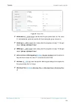
Page 34: ...ve characters Diming Value During DALI Bus Failure Off Defined Vale No Change in case of selecting Defined Value the ballast will switch to a customisable value 0 100 Figure 13 Group N Configuration F...

Page 35: ...more details ETS PARAMETERISATION When new ballasts become enabled see section 2 2 and assigned to a group new sub tabs one per ballast will be incorporated under the Group N tab being N the number o...

Page 36: ...ng percentage of 100 Dimming Limits perceptible limits that allow restricting the percentage value range of the control objects Note that the actual meaning of the values of these objects depends itse...

Page 37: ...possible to specify the luminosity level that the group will adopt when a general switch on order is executed either a fixed value configurable in parameters or the last value prior to the switch off...

Page 38: ...transition may be selected among the three different dimming times already defined An immediate transition can also be configured if desired Note in case of configuring dimming limits see section 2 5...

Page 39: ...the maximum configured value In case of selecting Defined Value o Value 0 100 On Off Dimming Time At Once Dimming Time 1 Dimming Time 2 Dimming Time 3 Relative Dimming 4 bits allows setting up the con...

Page 40: ...atus Objects tab Figure 17 Status Objects Send On Off Status enabled disabled enables sending a one bit object Group n On Off Status whenever the group is switched off 0 or on 1 Send Dimming Status en...

Page 41: ...RISATION Once the function has been enabled the Group n Custom On Off one bit object and a specific parameter tab will show in ETS Figure 18 Custom On Off This new screen allows setting up the specifi...

Page 42: ...fter a certain period or triggered through the corresponding bus object also with an optional delay in this case On the other hand the flashing function consists in switching the group on and off a ce...

Page 43: ...times Nothing the current time count will not be restarted Restart the time count of the On Duration will be restarted from zero Multiply the time count of the On Duration will become n times the con...

Page 44: ...ets a delay after the reception of value 1 through object Group n Simple Timer Off Delay 0 255 s min sets a delay after the reception of value 0 through object Group n Simple Timer Action in Case of R...

Page 45: ...ime immediate Assuming that the 1 labels correspond to the arrivals of the value 1 through the Group n Simple Timer and that the 0 labels correspond to the arrival of the value 0 the expected behaviou...

Page 46: ...up after the last repetition or after the reception PARAMETRIZACI N ETS Once the flashing function has been enabled the Group n Flashing one bit object will turn visible in order to let triggering an...

Page 47: ...sing to that group are ignored Receiving a lock order while running a sequence a flashing sequence or a timed action will stop the execution of that action ETS PARAMETERISATION Once this function has...

Page 48: ...d the ballasts of the group will remain off After recovering from a KNX bus power failure the ballasts of the group will recover their state previous to the power failure On the other hand opting for...

Page 49: ...s at the start up to inform about the initial state of the group This requires that the status objects have been enabled see section 2 5 5 Delay 0 255 s sets a delay before performing this sending 2 5...

Page 50: ...s such as fluorescent lighting which need to remain on for a certain time period before performing any light dimming To that end before the ballasts of the group have been steadily switched on for at...

Page 51: ...the Burn in mode at any time ETS PARAMETERISATION Once the Modes option has been enabled the following parameters will show in ETS Figure 25 Modes Burn in enabled disabled allows enabling the Burn in...

Page 52: ...100 255 h sets the time the Burn in mode should last Start Burn in After Programming enabled disabled sets whether the start up actions configured see section 2 5 9 should be applied the Burn in rest...

Page 53: ...ifferent enabled groups ETS PARAMETERISATION Once this function has been enabled the following object will show in ETS Scene Control one byte will execute or save the scene whose number is received th...

Page 54: ...cremented by 128 according to the KNX standard The specific action to be performed by each group on the execution of the scene can be selectively configured ETS PARAMETERISATION Figure 27 Scene N Scen...

Page 55: ...S Sequence Control one byte will trigger the sequence whose number is received through the object as detailed next Sequence Number Stop Start 1 0 128 2 1 129 64 63 191 Table 3 Sequence Control Sequenc...

Page 56: ...as the target dimming value the dimming type at once or smooth and the total length of the action prior to trigger the next one ETS PARAMETERISATION The Sequence N tab contains the following paramete...

Page 57: ...s parameter allows the execution of another sequence after the last action of the current one Each sequence allows enabling up to five actions Figure 30 Sequence example Action M enables action number...

Page 58: ...figured through the next parameter Time to Next Action 0 10 255 s min defines the length of the action i e the time it will take until the next action begins Send Luminosity During Sequence enabled di...

Page 59: ...4 Reset All ECGs 5 Manual Control 6 Scene Control 7 Burn in Control 8 Application Version It is possible to browse through them by pressing on and To enter any of the submenus please press OK To retur...

Page 60: ...sses that have not been assigned to any of the ballasts To step through the different cells please make use of the arrow buttons Note that only two rows are shown simultaneously to reach the other row...

Page 61: ...ast is assigned an individual group 17 32 previously assigned to another ballast the latter will change to No group To enter the ECG address assignment section please press To switch back to the upper...

Page 62: ...assignment and re connect the ballast which will be automatically assigned by DALIBOX Interface 64 32 the only address available To enter the ballast errors section please press 2 8 2 4 BALLAST ERROR...

Page 63: ...e associated object has not been enabled in parameters Note that this count is performed by DALIBOX Interface 64 32 according to the hours it maintains the ballast dimming level over 0 Figure 36 Opera...

Page 64: ...not be switched Figure 38 Switch All ECGs 2 8 5 RESET ALL ECGS This submenu allows resetting all the ballasts connected to the bus to their defaults thus removing their address assignments after whic...

Page 65: ...med are switch on switch off upward dimming and downward dimming After entering this submenu a group selection table will show on the upper section of the display Empty cells correspond to group numbe...

Page 66: ...ress on OK Figure 42 Scene Control After running or saving a scene a confirmation text will be shown respectively Scene N invoked or Scene N saved 2 8 8 BURN IN CONTROL This submenu allows checking th...

Page 67: ...ed in parameters it will still show up in the group selection table however the message Burn in state not available will be shown if trying to activate it 2 8 9 APPLICATION VERSION The Application Ver...

Page 68: ...0 No Error 1 Short Circuit 10 1 Bit I O C R W T DPT_Alarm 0 1 Error ECG Presence 0 No Error 1 ECG Presence Failure 11 2 Bytes I C W T DPT_DALI_Control_Gear_Diagnostics ECG and Group Diagnostic ECG and...

Page 69: ...319 330 341 352 363 1 Bit O C R T DPT_Switch 0 1 Group x On Off Status 0 Off 1 On 23 34 45 56 67 78 89 100 111 122 133 144 155 166 177 188 199 210 221 232 243 254 265 276 287 298 309 320 331 342 353 3...

Page 70: ...0 Burn in Inactive 1 Burn in Active 370 374 378 382 386 390 394 398 402 406 410 414 418 422 426 430 434 438 442 446 450 454 458 462 466 470 474 478 482 486 490 494 498 502 506 510 514 518 522 526 530...

Page 71: ...n and send us your inquiries about Zennio devices http support zennio com Zennio Avance y Tecnolog a S L C R o Jarama 132 Nave P 8 11 45007 Toledo Spain Tel 34 925 232 002 www zennio com info zennio c...

Reviews: