background image


DALIBOX Broadcast 6CH/4CH


http://www.zennio.com


Soporte técnico:


http://support.zennio.com 


14 


Error Objects

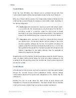
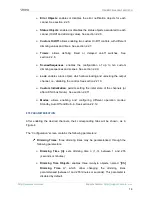
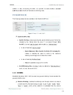
: enables  or disables  the error notification objects for each 

cannel. See section  2.2.5. 


Status Objects

: enabled or disables the status objects associated to each 

cannel (On/Off and dimming value). See section  2.2.6. 


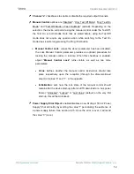
Custom On/Off

: allows enabling two custom On/Off controls, with different 

dimming values and times. See section  2.2.7. 


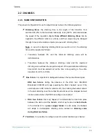
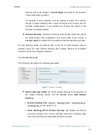
Timers

:  allows  defining  timed or delayed on/off switches. See 

section  2.2.8. 


Scenes/Sequences

:  enables the configuration of up to ten custom 

dimming sequences and scenes. See section  2.2.9. 


Lock

: enables a lock object, which allows locking and unlocking the output 

channel, i.e., disabling the control. See section  2.2.10. 


Custom Initialization

:  permits setting the  initial  state of the channels (or 

after a KNX bus failure). See section  2.2.11. 


Modes

:  allows  enabling  and  configuring  different  operation  modes: 

Standby, Auto Off and Burn-in. See section  2.2.12. 

ETS PARAMETERISATION 

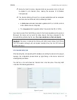
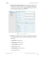
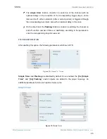
After enabling the desired channels, their corresponding tabs will be shown, as in 

Figure 4. 

The “Configuration” screen contains the following parameters: 


Dimming Times

: three dimming times may be parameterised, through the 

following parameters: 


Dimming Time [n]

: sets dimming time 

(1-3), between 1 and 255 

(seconds or minutes). 


Dimming Time Objects

: enables three two-byte objects, named “

[Ch] 

Dimming Time n

”, which allow changing the dimming times 

parameterised (between 1 and 255 minutes or seconds). This parameter is 

disabled by default. 

Summary of Contents for DALIBOX ZDI-DLB6

Page 1: ...DALIBOX Broadcast 6CH 4CH KNX DALI Interface for 6 4 Channel Broadcast Control ZDI DLB6 ZDI DLB4 MANUAL DE USUARIO Application Program Version 1 0 Manual Edition 1 0 _a www zennio com...

Page 2: ...6 2 Configuration 7 2 1 General Configuration 9 2 2 Channels 13 2 2 1 Main Configuration 13 2 2 2 Limits 16 2 2 3 Switch On Off 17 2 2 4 Dimming 18 2 2 5 Error Objects 20 2 2 6 Status Objects 23 2 2...

Page 3: ...Support for up to 20 ballasts per channel and therefore up to 120 ballasts 6CH model or up to 80 ballasts 4CH model in total 110V or 230V power supply Ballast swap with automatic address re assignment...

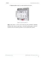
Page 4: ...ugh the on board pushbuttons and LEDs Figure 1 DALIBOX Broadcast 6CH Note certain figures or sections of this manual may refer specifically to DALIBOX Broadcast 6CH However please bear in mind that ev...

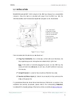
Page 5: ...s button is held while plugging the device into the KNX bus the device will enter into safe mode In such case the LED will blink in red every 0 5 seconds Output Channels 1 slots for the connection of...

Page 6: ...uorescent lamps may cause the remaining lamps flash briefly Fluorescent lamp ballasts need an extra time to switch off the load when a non immediate regulation to 0 is commanded Certain ballast models...

Page 7: ...es being possible to modify them through communication objects Up to three different dimming times are available Dimming limits i e maximum and minimum lighting levels Minimum luminosity level reachab...

Page 8: ...p failure Special operation modes Standby mode that allows notifying an external actuator after switching off a channel so the power supply to the ballasts in such channel can be interrupted thus redu...

Page 9: ...nnel Manual operation can be done in two different ways named as Test On mode for testing purposes during the configuration of the device and Test Off mode for a normal use anytime Whether both only o...

Page 10: ...will be contrary to that of the previous regulation although the first time the regulation will always be upwards unless the current level is already the maximum one in such case the regulation will...

Page 11: ...om the KXN bus related to the channel operation will be ignored Moreover the device will not send the status objects that may correspond to the manual actions performed by the user The only exceptions...

Page 12: ...l Control parameter provides an optional procedure for locking the manual control in runtime When this checkbox is enabled object Manual Control Lock turns visible as well as two more parameters Value...

Page 13: ...ng value and the maximum dimming value will take the proportional part of the parameterised dimming time which must be understood as the time corresponding to the entire transition from 0 to 100 Bus f...

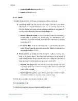
Page 14: ...cking and unlocking the output channel i e disabling the control See section 2 2 10 Custom Initialization permits setting the initial state of the channels or after a KNX bus failure See section 2 2 1...

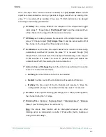
Page 15: ...ch off or Defined Value the ballast will switch to a customisable value between 0 and 100 Figure 4 Channel x Configuration Functions checkboxes for enable or disable several additional functionalities...

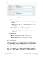
Page 16: ...percentage of 1 Economic Mode maximum luminosity level the ballast will be allowed to reach It determines the actual luminosity level that will correspond to a dimming percentage of 100 Dimming Limit...

Page 17: ...imming Limits Minimum Dimming Value the available range is 0 to 100 Maximum Dimming Value the available range is 0 to 100 2 2 3 SWITCH ON OFF DALIBOX Broadcast 6CH 4CH lets configuring the general On...

Page 18: ...Last On Value default option or Defined Value In case of selecting Last On Value o Reach Maximum after a Switch On Order if it s Already On enables or disables the option to switch to the maximum dimm...

Page 19: ...e object is provided for the reception of the absolute dimming orders For both dimming modes the dimming time for the 0 to 100 transition may be selected among the three different dimming times alread...

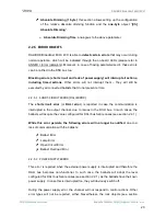
Page 20: ...resent errors 2 2 5 1 SHORT CIRCUIT ERROR DALI ERROR The short circuit error or DALI error is reported in case the communication is interrupted in the output channel due to issues in the DALI bus In s...

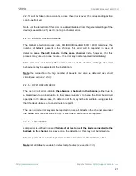
Page 21: ...pected in the installation Note the connection of a high number of ballasts may also be detected as a short circuit see section 2 2 5 1 2 2 5 4 OPEN CIRCUIT ERROR The open circuit error indicates the...

Page 22: ...e current number of ballasts as correct To replace an erroneous ballast with a new ballast it is advisable to wait for the detection of the ballast error and to connect the new ballast only after havi...

Page 23: ...the Cx Error Lamp Failure object which will be sent periodically with value 1 in case of detecting a lamp failure in at least one of the ballasts connected to the channel After the error is over it w...

Page 24: ...ming value between 0 and 100 whenever it changes Enabling this parameter brings up an addition one Sending Period defines the sending cycle time 1 to 255 seconds of the status object during a dimming...

Page 25: ...orementioned object Dimming Value for Bit Value 1 sets a specific dimming percentage 0 to 100 to be applied to the channel when a 1 is received Dimming Time for Bit Value 1 At Once Dimming Time 1 Dimm...

Page 26: ...in this case On the other hand the flashing function consists in switching the channel on and off a certain number of times or indefinitely according to the parameters once the corresponding object i...

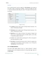
Page 27: ...before being automatically switched off unless the value 0 is received through Cx Simple Timer which will switch the channel off immediately in the range 0 to 255 seconds or minutes The value 0 defau...

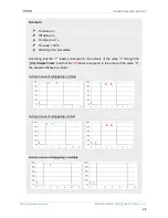
Page 28: ...g time immediate Assuming that the 1 labels correspond to the arrivals of the value 1 through the Cx Simple Timer and that the 0 labels correspond to the arrival of the value 0 the expected behaviour...

Page 29: ...ge during the sequence in the range 1 to 255 seconds or minutes Repetitions sets the number of iterations of the sequence between 0 and 255 The value 0 default option causes an endless repetition unti...

Page 30: ...rformed or restarting the one currently running by sending the value 1 as well as interrupting the current sequence value 0 Note the Cx Start Stop Sequence object only applies to sequences and has no...

Page 31: ...ype At Once Dimming Time 1 Dimming Time 2 Dimming Time 3 See section 2 2 1 In this case it will be also possible to save scenes If a scene saving order values 128 to 191 is received the current dimmin...

Page 32: ...out the Action the dimming speed will adapt so that transition lasts for all the action time configured Action time defines the duration of the action i e the time it will take until the next action b...

Page 33: ...bit object which will allow locking and unlocking the related channel Channel locking causes that any bus orders addressing to that channel are ignored Receiving a lock order while running a sequence...

Page 34: ...vious State to recover the status previous to the lock order and Last Order to apply the status corresponding to the last order received during the lock state in case of not having received any order...

Page 35: ...ed Value the channel will start at a specific dimming level between 0 and 100 configured in Value Send Status if enabled the status objects will be sent to the bus at the start up to inform about the...

Page 36: ...s inactive to make it possible that the ballasts are powered during their initialisation Some other situations imply sending the Standby object A power supply error A short circuit error DALI error Du...

Page 37: ...steadily switched on for at least the configured time it will only be possible to switch the loads off or to regulate them to 100 In case of having configured any limits either luminosity limits or d...

Page 38: ...tomatic switch off of the channel if it is found to be steady i e without receiving further dimming orders at a certain dimming value or threshold for at least a certain amount of time configurable Th...

Page 39: ...value for more than the threshold time Threshold Time time count before triggering the Auto Off mode between 1 255 seconds or minutes 10 seconds by default Burn in allows enabling the Burn in function...

Page 40: ...ply Error notified through a specific LED Figure 23 Power Supply Error Channel dependent errors channel errors are indicated through the LED corresponding to the channel The error can be identified by...

Page 41: ...Dec by 100 0x2 Dec by 50 0x3 Dec by 25 0x4 Dec by 12 0x5 Dec by 6 0x6 Dec by 3 0x7 Dec by 1 0x8 Stop 0x9 Inc by 100 0xA Inc by 50 0xB Inc by 25 0xC Inc by 12 0xD Inc by 6 0xE Inc by 3 0xF Inc by 1 Cx...

Page 42: ...C W DPT_Start 0 1 Cx Burn in Mode 0 Stop Burn in 1 Start Burn in 20 44 68 92 116 140 1 Bit O C T R DPT_State 0 1 Cx Burn in Mode Status 0 Burn in Inactive 1 Burn in Active 21 45 69 93 117 141 1 Bit O...

Page 43: ...tus consultas sobre los dispositivos Zennio http support zennio com Zennio Avance y Tecnolog a S L C R o Jarama 132 Nave P 8 11 45007 Toledo Spain Tel 34 925 232 002 Fax 34 925 337 310 www zennio com...

Reviews: