© Zennio Avance y Tecnología S.L.
Edition 7
Further information
Page 2/2
SAFETY INSTRUCTIONS AND ADDITIONAL NOTES
•
Installation should only be performed by qualified professionals according to the laws and regulations applicable in each country.
•
Do not connect the mains voltage nor any other external voltage to any point of the KNX bus; it would represent a risk for th e entire
KNX system. The facility must have enough insulation between the mains (or auxiliary) voltage and the KNX bus or the wires of other
accessories, in case of being installed.
•
The facility must be equipped with a device that ensures the omnipolar sectioning. Installation of a 10 A mini-circuit-breaker is
recommended. To prevent accidents, it must remain open in case of manipulation of the device.
•
The device has a short-circuit protection fuse that, in case of activation, should only be rearmed or replaced by the Zennio technical
service.
•
This device contains a security short-circuit proof transformer.
•
Once the device is installed (in the panel or box), it must not be accessible from outside.
•
For indoor use only.
•
Keep the device away from water (condensation over the device included) and do not cover it with clothes, paper or any other material
while in use.
•
This device contains a security short-circuit proof transformer.
•
The WEEE logo means that this device contains electronic parts and it must be properly disposed of by following the instructi ons at
https://www.zennio.com/en/legal/weee-regulation.
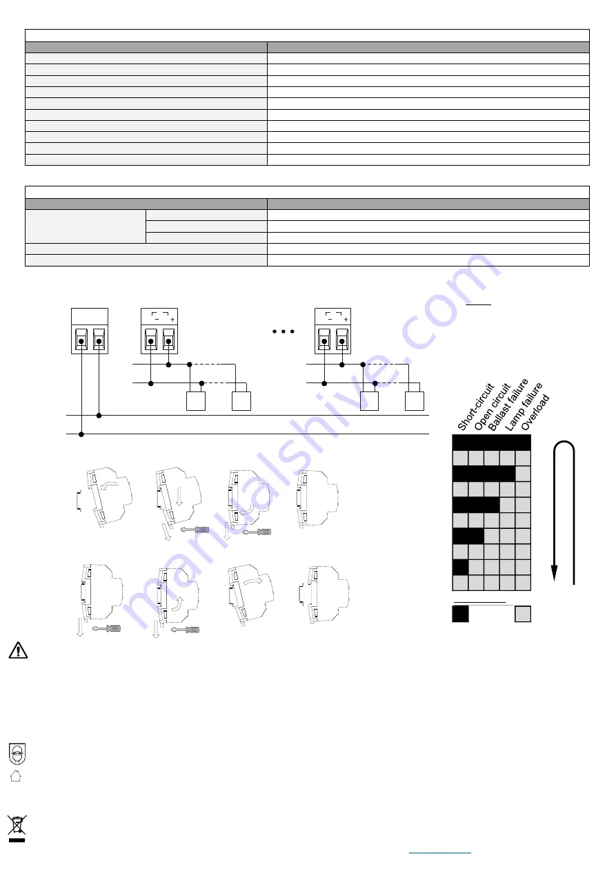
OUTPUTS SPECIFICATIONS AND CONNECTIONS OF DALI CHANNELS
CONCEPT
DESCRIPTION
Number of channels
6
Output type / Voltage
DALI bus / 16 VDC SELV
Maximum current per channel
40 mA
Maximum DALI ballasts per channel²
20
Maximum length of cable
300 m (@ 1.5 mm²)
Short-circuit protection
YES
Overload protection
YES
Over-voltage protection
YES
Connection method
Screw terminal block (0.5 Nm max.)
Cable cross-section
0.5-2.5 mm² (IEC) / 26-12 AWG (UL)
² One DALI address is considered per DALI ballast.
EXTERNAL POWER SUPPLY SPECIFICATIONS AND CONNECTIONS
CONCEPT
DESCRIPTION
Power supply protection
fuse
Voltage
250 V
Current
4 A
Response type
F (Fast acting)
Connection method
Screw terminal block (0.5 Nm max.)
Cable cross-section
1.5-4 mm² (IEC) / 26-10 AWG (UL)
WIRING DIAGRAMS
Figure 2. Error notification through
DALI channel status LED
Sh
or
t-
cir
cu
it
O
pe
n
cir
cu
it
Ba
lla
st
fa
ilu
re
La
m
p
fa
ilu
re
O
ve
rlo
ad
Ti
me
(
s)
0.5
1.0
1.5
2.0
2.5
3.0
3.5
4.0
4.5
5.0
Description:
LED On
LED Off
Ti
me
(
s)
T
im
e (s
)
Description:
L
N
N
L
+
-
DA
DA
1
DALI BUS 1
+
-
DA
DA
6
DALI BUS 6
Ballast
1.1
Ballast
1.
n
(
n
≤20)
110/230 V
AC
50/60 Hz
Ballast
6.1
Ballast
6.
n
(
n
≤20)
Notes
:
·
Electrical connection between
different DALI channels must
be avoided.
·
In case of ballast replacement,
please pay attention to the
defined steps on the manual.
Attaching DALIBOX Broadcast 6CH to DIN rail:
Removing DALIBOX Broadcast 6CH from DIN rail:


