© Zennio Avance y Tecnología S.L.
Edition 5
Futher information
Page 2/2
SAFETY INSTRUCTIONS AND ADDITIONAL NOTES
•
Installation should only be performed by qualified professionals according to the laws and regulations applicable in each cou ntry.
•
Do not connect the mains voltage nor any other external voltage to any point of the KNX bus; it would represent a risk for the entire
KNX system. The facility must have enough insulation between the mains (or auxiliary) voltage and the KNX bus or the wires of other
accessories, in case of being installed.
•
The facility must be equipped with a device that ensures the omnipolar sectioning. Installation of a 10A mini-circuit-breaker is
recommended. To prevent accidents, it must remain open in case of manipulation of the device.
•
Once the device is installed (in the panel or box), it must not be accessible from outside.
•
Keep the device away from water (condensation over the device included) and do not cover it with clothes, paper or any other material
while in use.
•
The WEEE logo means that this device contains electronic parts and it must be properly disposed of by following the instructions at
https://www.zennio.com/en/legal/weee-regulation.
•
This device contains software subject to specific licences. For details, please refer to http://zennio.com/licenses.
OUTPUTS SPECIFICATIONS AND CONNECTIONS
CONCEPT
DESCRIPTION
Number of outputs
1
Output type
Relays based control device
Maximum recommended load per output
100W
Minimum load per output
30W
Short-circuit protection
NO
Overload protection
NO
Connection method
Screw terminal block
Cable cross-section
0.5-2,5mm² (IEC) / 26-12AWG (UL)
Outputs per common
1
Maximum response time
15ms
Mechanical lifetime (min. cycles)
3 000 000
Electrical lifetime (min. cycles)
100000 @ 8A / 25000 @ 16A (VAC)
¹ Lifetime values could change depending on the load type.
EXTERNAL POWER SUPPLY SPECIFICATIONS AND CONNECTIONS
CONCEPT
DESCRIPTION
Voltage
230VAC
Connection method
Screw terminal block
Cable cross-section
0.5-2,5mm² (IEC) / 26-12AWG (UL)
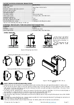
⚠
In order to ensure the expected
status of the relays, please check
that the device is connected to the
KNX bus before energizing the
power circuit.
⚠
Use for ceiling fans. Do not
use
other
load
to
avoid
damages
.
WIRING DIAGRAMS
Figure 2: Wiring diagram of a fan
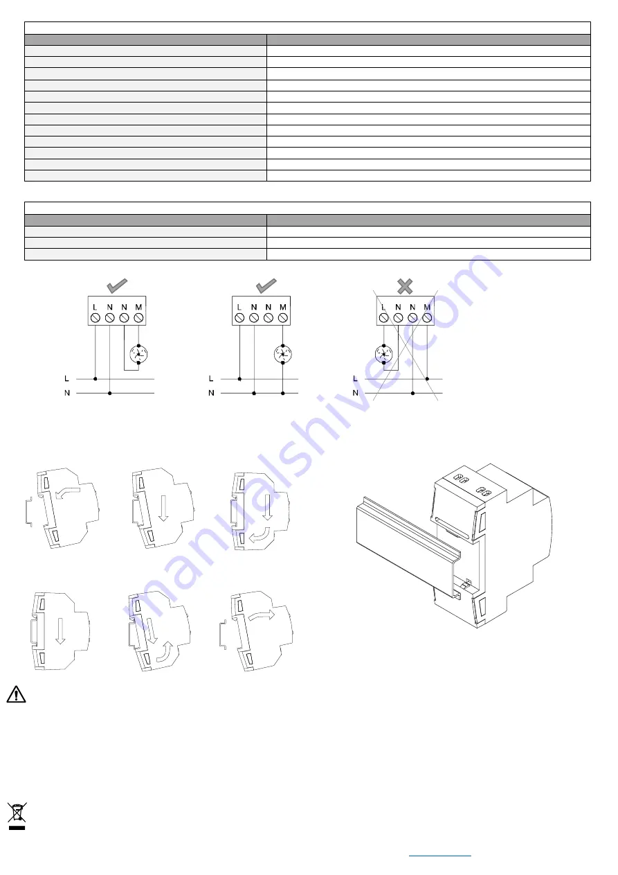
Figure 3: Mounting FANinBOX 230V 1CH on
DIN rail
Attaching FANinBOX 230V 1CH to DIN rail:
Removing FANinBOX 230V 1CH from DIN rail:


