background image


inBOX 24 vT / inBOX 20 vT


https://www.zennio.com


Technical Support:


https://support.zennio.com


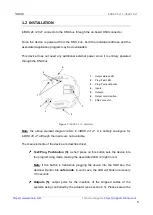
connection by means of the on-board screws. 


Inputs  (4)

:  input  ports  for  the  insertion  of  the  stripped  cables  of  external 

elements such as switches / motion detectors / temperature probes, etc. One 

of the two cables of each element needs to be connected to one of the slots 

labelled 

“1”  to  “4”,  while  the  other  cable  should  be  connected  to  the  slot 

labelled 

as “C”. Note that all the external input devices share the “C” slot for 

one  of  the  two  cables.  Please  secure  the  connection  by  means  of  the  on-

board screws. 

To get detailed information about the technical features of this device, as well as on the 

installation  and  security  procedures,  please  refer  to  the  corresponding 

Datasheet

bundled with the original package of the device and also available at 

www.zennio.com


1.3


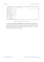
START-UP AND POWER LOSS 

During the start-up of the device, the Test/Prog. LED will blink in blue colour for a few 

seconds  before  the  device  is  ready.  External  orders  will  not  be  executed  during  this 

time, but afterwards.  

Depending  on  the  configuration,  some  specific  actions  will  also  be  performed  during 

the  start-up.  For  example,  the  integrator  can  set  whether  the  output  channels  should 

switch to  a  particular  state  and  whether the  device  should  send  certain objects  to the 

bus  after  the  power  recovery.  Please  consult  the  next  sections  of  this  document  for 

further details. 

On the other hand, when a bus power failure takes place, the device will interrupt any 

pending actions, and will save its state so it can be recovered once the power supply is 

restored. For safety reasons,  the 

shutter channel

 will be stopped (i.e., the relays will 

open) if a power loss takes place, while the individual outputs will switch to the specific 

state configured in ETS (if any). 

Summary of Contents for inBOX 24 vT

Page 1: ...inBOX 24 vT inBOX 20 vT Multifunction Actuator for Flush Mounting ZIOIB24VT USER MANUAL ZIOIB20VT ds kmfroi Application program version 1 2 1 4 User manual edition 1 4 _b www zennio com...

Page 2: ...Up and Power Loss 6 2 Configuration 7 2 1 General 7 2 2 Inputs Only inBOX 24 vT 9 2 2 1 Binary Input 9 2 2 2 Temperature Probe 9 2 2 3 Motion Detector 9 2 3 Outputs 10 2 3 1 Manual Control 10 2 4 Logi...

Page 3: ...w zennio com Technical Support https support zennio com 3 DOCUMENT UPDATES Version Changes Page s 1 4 _b Erratum correction on functionalities listed for inBOX 24 vT Separation of communication object...

Page 4: ...2 individual ON OFF outputs 4 multi purpose inputs only in inBOX 24 vT configurable as Temperature probe either models provided by Zennio or other NTC temperature probes from other suppliers being in...

Page 5: ...entirely analogous for inBOX 20 vT although the inputs are not available The main elements of the device are described next Test Prog Pushbutton 3 a short press on this button sets the device into th...

Page 6: ...device and also available at www zennio com 1 3 START UP AND POWER LOSS During the start up of the device the Test Prog LED will blink in blue colour for a few seconds before the device is ready Exter...

Page 7: ...ATION From the General screen it is possible to activate deactivate all the required functionality Figure 2 Default screen Once activated Inputs only on inBOX 24 vT Outputs Logic Functions Thermostats...

Page 8: ...dical Alive Notification this parameter lets the integrator incorporate a one bit object to the project Heartbeat Object to Send 1 that will be sent periodically with value 1 to notify that the device...

Page 9: ...Zennio 2 2 1 BINARY INPUT Please refer to the specific user manual Binary Inputs available in the inBOX 24 vT product section at the Zennio website www zennio com 2 2 2 TEMPERATURE PROBE Please refer...

Page 10: ...therefore available per output Manual operation can be done in two different ways named as Test On Mode for testing purposes during the configuration of the device and Test Off Mode for a normal use...

Page 11: ...ed the device will act over the output according to the length of the button press and to the current state A long press makes the shutter start moving upwards or downwards depending on the button bei...

Page 12: ...leaving the Test On mode the status objects will recover the values they had prior to entering Test On As the device is never aware of the actual position of the shutter as the shutter drive does not...

Page 13: ...ng pressing the Prog Test button Lock Manual Control unless the above parameter has been Disabled the Lock Manual Control parameter provides an optional procedure for locking the manual control in run...

Page 14: ...execution of each function can depend on a configurable condition which will be evaluated every time the function is triggered through specific parameterizable communication objects The result after e...

Page 15: ...24 vT implements one Zennio thermostat which can be enabled and configured independently Please refer to the specific Zennio Thermostat user manual available in the inBOX 24 vT product section at the...

Page 16: ...hat to send to the KNX bus in both cases a shutter order a thermostat setpoint or mode switch order a constant value a scene Only the trigger object and the twelve status objects are required to be bi...

Page 17: ...off takes off Scene if checked object ML General Switch off Scene will be enabled which will send a scene run save order configurable in Action and Scene Number whenever the general switch off takes...

Page 18: ...https support zennio com 18 when the courtesy switch on takes place in contrast to object ML General Switch Off Binary Object which sends the value 0 during the general switch off as explained above...

Page 19: ...pending for that output or that channel such temporisation will be interrupted and only the delay and the action of the new scene will be executed ETS PARAMETERISATION Prior to setting the scene tempo...

Page 20: ...f the scene temporisation Therefore parameter Scene m Z Delay defines the delay that will be applied to the action defined in Z for the execution of scene m where Z may be a specific individual output...

Page 21: ...191 Save 1 64 6 17 1 Bit I C W DPT_BinaryValue 0 1 Ox On Off N O 0 Open Relay 1 Close Relay 1 Bit I C W DPT_BinaryValue 0 1 Ox On Off N C 0 Close Relay 1 Open Relay 7 18 1 Bit O C R T DPT_BinaryValue...

Page 22: ...0 Raise 1 Lower 43 1 Bit I C W DPT_Step 0 1 CA Auto Stop Step 0 Stop StepUp 1 Stop StepDown 1 Bit I C W DPT_Step 0 1 CA Auto Stop 0 Stop 1 Stop 44 1 Byte I C W DPT_Scaling 0 100 CA Auto Shutter Positi...

Page 23: ...00 670760 00 185 186 187 188 189 190 191 192 193 194 195 196 197 198 199 200 4 Bytes I C W DPT_Value_4_Count 2147483648 2147483647 LF 4 Byte Data Entry x 4 Byte Data Entry 201 202 203 204 205 206 207...

Page 24: ...urce 1 External Sensor Temperature 7 2 Bytes I C W DPT_Value_Temp 273 00 670433 28 Tx Temperature Source 2 External Sensor Temperature 8 2 Bytes O C R T DPT_Value_Temp 273 00 670433 28 Tx Effective Te...

Page 25: ...W DPT_Switch 0 1 Tx Main System Heat 0 System 1 1 System 2 30 1 Bit I C W DPT_Enable 0 1 Tx Enable Disable Secondary System Cool 0 Disable 1 Enable 31 1 Bit I C W DPT_Enable 0 1 Tx Enable Disable Sec...

Page 26: ...es O C R T DPT_Value_Temp 273 00 670433 28 Ix Current Temperature Temperature Sensor Value 67 71 75 79 1 Bit O C R T DPT_Alarm 0 1 Ix Overcooling 0 No Alarm 1 Alarm 68 72 76 80 1 Bit O C R T DPT_Alarm...

Page 27: ...Light On Off Switching 0 1 1 Byte C T DPT_SceneControl 0 63 128 191 Ix Short Press Run Scene Sending of 0 63 1 Byte C T DPT_SceneControl 0 63 128 191 Ix Short Press Save Scene Sending of 128 191 1 Bit...

Page 28: ...witching of 0 1 Stop Step Up Down 4 Bit C T DPT_Control_Dimming 0x0 Stop 0x1 Dec by 100 0x7 Dec by 1 0x8 Stop 0xD Inc by 100 0xF Inc by 1 Ix Long Press Brighter Long Pr Brighter Release Stop 4 Bit C T...

Page 29: ...1 Ix Open Circuit Error 0 No Error 1 Open Circuit Error 110 139 168 197 1 Bit O C R T DPT_Alarm 0 1 Ix Short Circuit Error 0 No Error 1 Short Circuit Error 111 140 169 198 1 Byte O C R T DPT_Scaling...

Page 30: ...BinaryValue 0 1 Ox On Off N O 0 Open Relay 1 Close Relay 1 Bit I C W DPT_BinaryValue 0 1 Ox On Off N C 0 Close Relay 1 Open Relay 226 237 1 Bit O C R T DPT_BinaryValue 0 1 Ox On Off Status 0 Output Of...

Page 31: ...p 0 1 CA Auto Stop 0 Stop 1 Stop 263 1 Byte I C W DPT_Scaling 0 100 CA Auto Shutter Positioning 0 Top 100 Bottom 264 1 Byte I C W DPT_Scaling 0 100 CA Auto Slats Positioning 0 Open 100 Closed 265 1 Bi...

Page 32: ...mpo 273 00 670760 00 340 341 342 343 344 345 346 347 4 Bytes I C W DPT_Value_4_Count 2147483648 2147483647 LF 4 Byte Data Entry x 4 Byte Data Entry 348 349 350 351 352 353 354 355 356 357 1 Bit O C R...

Page 33: ...n and send us your inquiries about Zennio devices https support zennio com Zennio Avance y Tecnolog a S L C R o Jarama 132 Nave P 8 11 45007 Toledo Spain Tel 34 925 232 002 www zennio com info zennio...

Reviews: