


IRSC Plus
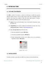
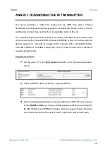
Technical Support:
9
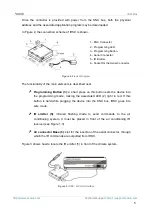
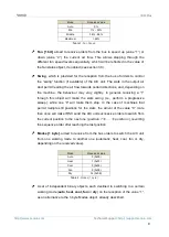
Mode
Received value
Auto
0%
Min
1% - 33%
Middle
34% - 66%
Maximum
> 66%
Table 1.
Fan Speed
Fan [1 bit]
, aimed to receive orders from the bus to speed up
(value “1”) or
down (value “0”) the current air flow. This allows stepping through the
different fan speed levels sequentially, which will be reflected in the value of
the fan status object, if enabled (see section 3.3).
Swing
, which is provided for the reception from the bus of orders to control
the “swing” function (if available) of the A/C unit. The slats in the output air
duct permit leading the air flow towards certain directions, and, depending on
the machine, the behaviour may vary slightly. In general, receiving a
“1”
through this object will make the slats
swing
(i.e., perform a progressive
sweep), while one
“0” will make them stop. In the case of machines that
permit multiple still positions for the slats, the arrival of the value
“0” more
than once will make IRSC send the A/C unit successive orders to switch from
the current position to the next one (
position 1
…
position n
), reverting
the sequence order after reaching the last position.
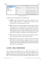
Modes [1 byte]
, aimed to receive from the bus orders to switch the A/C unit
from one working mode to another one (automatic, heat, cool, fan or dry,
depending on the received value).
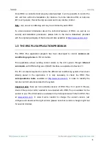
Mode
Received value
Auto
0 (0x00)
Heat
1 (0x01)
Cool
3 (0x03)
Fan
9 (0x09)
Dry
14 (0x0E)
Table 2.
Modes (1 byte)
A set of independent binary objects, each destined to switching to a certain
working mode (
auto
,
heat, cool, fan
or
dry
) on the reception of the value
“1”,
as an alternative to the 1-byte Modes object, already described.


