


IRSC Zone
http://www.zennio.com
Technical Support:
http://zennioenglish.zendesk.com
23
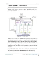
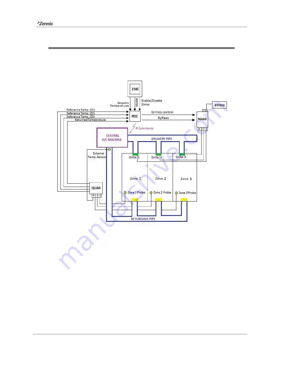
ANNEX I. INSTALLATION SCHEME
Figure 11 shows a typical scheme of an installation with 3 different climate zones,
controlled by an IRSC Zone.
Figure 11.
Scheme Installation example
The IRSC interface (programmed with the IRSC Zone application program) carries out
the thermostatic control of the installation by receiving data from an external touch
panel (InZennio Z38i or InZennio Z41) and from a sensor (QUAD), which measures the
temperatures of the different enabled zones in the installation. With this input data, and
according to the configuration parameterised in ETS, IRSC Zone will send orders, via
IR commands, to the central A/C machine to acclimatise the installation zone by zone,
as desired.
To get optimal acclimatization, it is recommended to install the external sensor in the
inner side of the returning pipe, as closest as possible to the central A/C machine.


