ZENN
iO
AVANCE Y TECNOLOGÍA
vwww.zennio.com
4
4
1.2. INSTALLATION
KES Energy Saver connects to the KNX bus via the bus connecting terminals.
The input channels are connected to KES through the terminal block with screws included in the
device packaging.
Once KES is provided with power supply from the KNX bus, both the individual address and the
associated application programme can be downloaded.
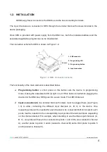
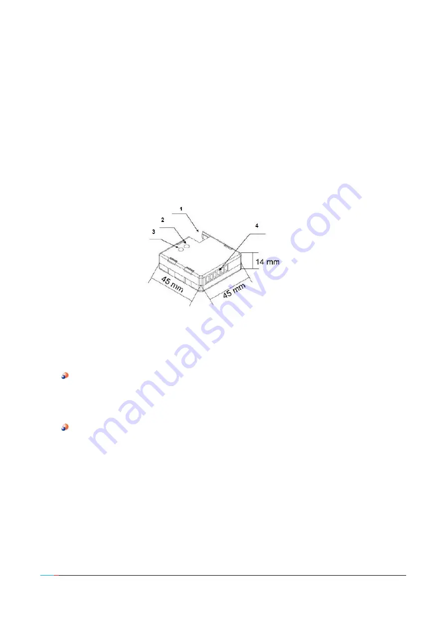
The connection scheme for KES is shown on Figure 1.2:
Figure 1.2. KES. Connection scheme
The functionality of the main elements is described below.
Programming button:
a short press on this button sets the device to programming
mode, making the associated LED (2) light in red. If this button is held while plugging the
device into the KNX bus, KES goes into secure mode. The LED blinks red.
Input connection (4)
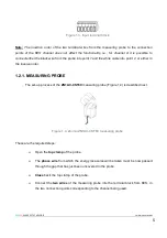
: the terminal block with screws must be plugged here (see Figure
1.3) to allow connecting the different input channels (A, B, C) to the device. One
measuring probe will be needed for each channel to be connected. Both terminals of each
probe must be inserted in the corresponding input points of the terminal block, depending
on the channel desired. For example, when intending to use the three input channels (A,
B, C), one probe will have to be connected to points 1 and 2 (the ones related to channel
A), another probe to points 3 and 4 (related to channel B) and a third probe to points 5
and 6 (related to channel C).
1.- KNX connector
2.- Programming LED
3.- Programming button
4.- Input connection

