ZENN
iO
AVANCE Y TECNOLOGÍA
vwww.zennio.com
5
5
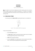
Figure 1.3. Input terminal block
Note:
The insertion order of the two terminal wires from the measuring probe to the connection
points of the KES channel does not affect the functionality, i.e., for channel A it is possible to
connect either the black wire from the probe into point 1 and the white cable into point 2, or either in
the inverse order.
1.2.1. MEASURING PROBE
The set-up process of the
ZN1AC-CST60
measuring probe (Figure 1.4) is described next.
Figure 1.4. Zennio ZN1AC-CST60 measuring probe
These are the required steps:
Open the
top clamp
of the probe.
The
phase wire
from which the energy measures will be taken must be now passed
through the gap that has just been uncovered in the probe.
Close
back the top clamp of the probe.
Connect the
two wires
of the measuring probe into the terminal block from KES, in
the two connection points corresponding to the channel being used.

