KLIC-DD3
http://www.zennio.com
Technical Support:
http://support.zennio.com
4
1.2
INSTALLATION
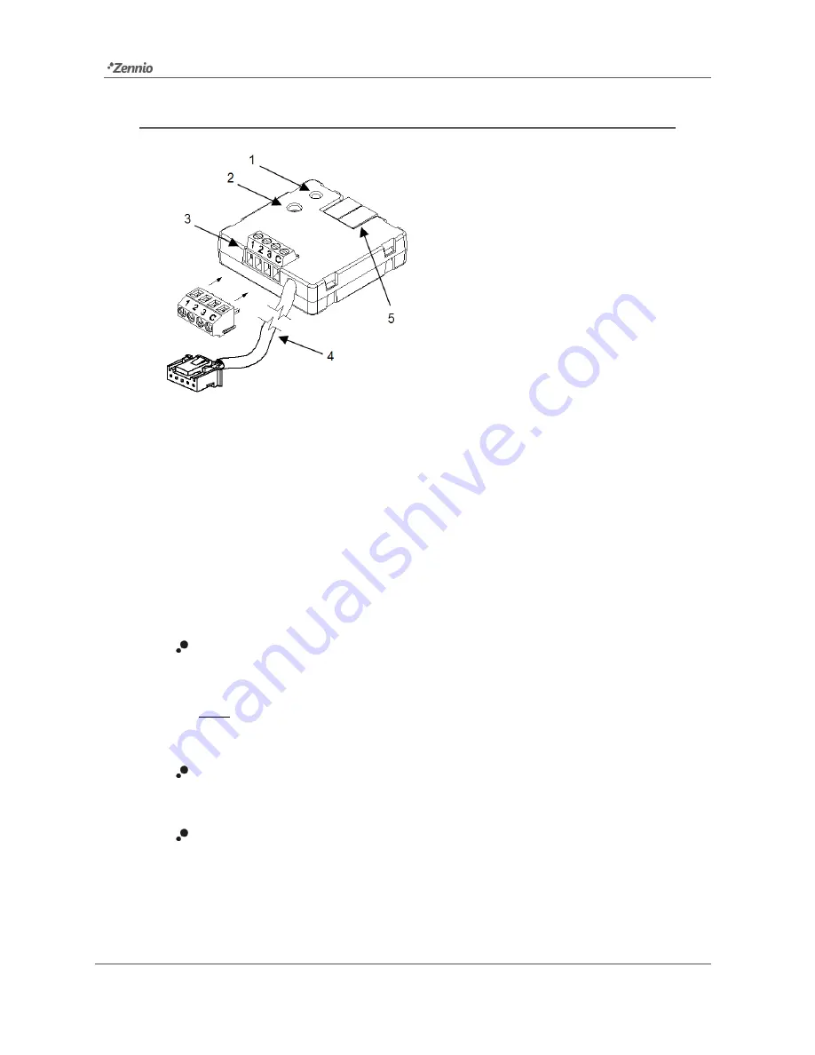
Figure 1.
Element scheme.
KLIC-DD3 connects to the KNX bus via the corresponding built-in terminal (5). Once
the device is provided with power from the KNX bus, both the physical address and the
KLIC-DD3 application program can be downloaded.
This device does not need any external power as it is entirely powered through the
KNX bus.
The remaining elements are described next.
Prog./Test button (2)
: a short press on this button will set the device into the
programming mode, making the associated LED (1) light in red.
Note
:
if this button is held while plugging the device into the KNX bus, the
device will enter into safe mode. The LED will blink in red every 0.5 seconds
Analogue-Digital Inputs (3)
: input ports for the stripped cables of external
elements such as switches, motion detectors, temperature probes, etc.
Communication cable (4)
: 5-wire cable with S21 connector that will connect
KLIC-DD3 and the A/C unit. The other end of the cable, therefore, is intended
to be connected to the S21 connector in the PCB board of the internal unit.
1. Prog./Test LED indicator.
2. Prog./Test button.
3. Analogue/digital inputs.
4. S21 communication cable.
5. KNX connector.


