background image


KLIC-DI SKY


http://www.zennio.com


Technical Support:


http://support.zennio.com


13 

3


ETS PARAMETERISATION  

To  begin  with  the  parameterisation  process  of  the  KLIC-DI  interface  it  is  necessary, 

once  the  ETS  programme  has  been  opened,  to  import  the  database  of  the  product 

(

KLIC-DI SKY

 application programme). 

Next, the device should be added to the project. And then, one right-click on the device 

will permit selecting "Edit parameters", in order to start the configuration. 

In the following sections a detailed explanation is provided about how to parameterise 

the different functionalities of the device in ETS. 

3.1


DEFAULT CONFIGURATION 

This section shows the default configuration the device configuration starts from. 


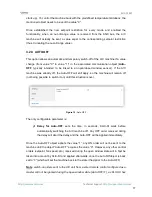
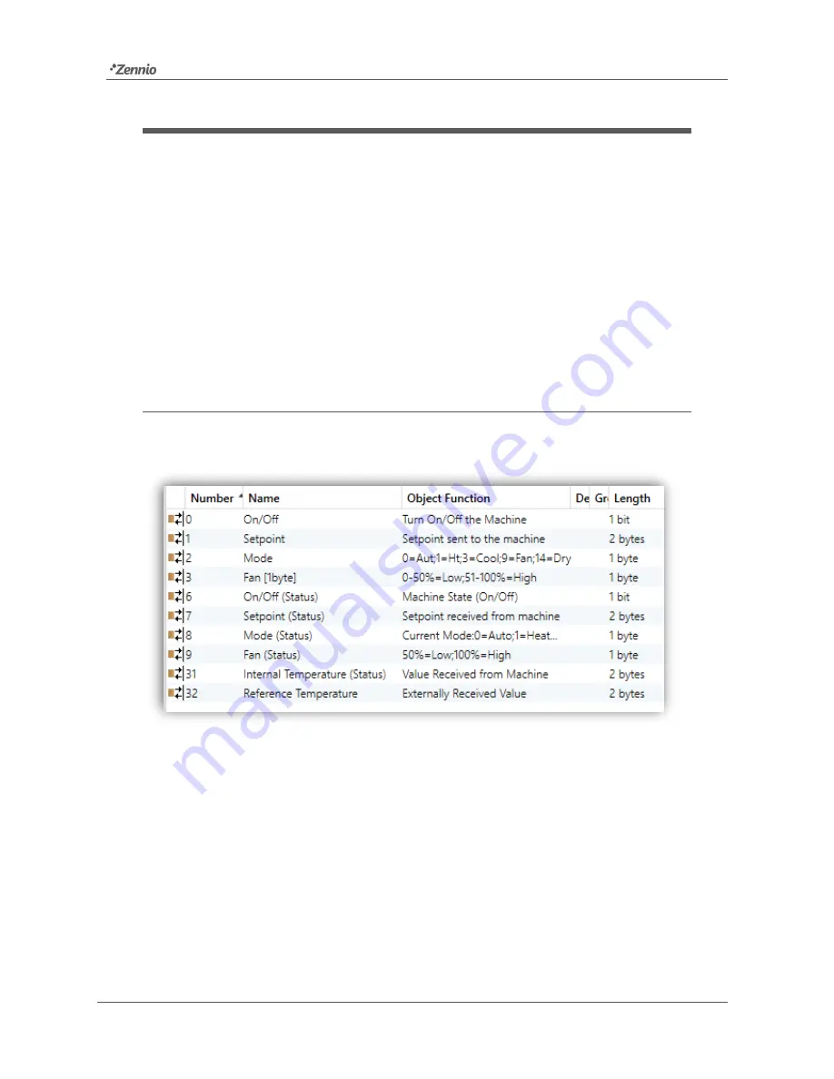
Figure 5. 

Default Topology


The default topology window (Figure 5) contains the communication objects associated 

to  the  reception  of  the  control  orders  for  the  basic  operation  of  the  A/C  unit:  on/off, 

setpoint, mode and fan. In addition, the corresponding status objects (which will report 

the updated state values of the A/C system to the KNX bus) are also shown. 

When  entering  the  parameter  edition  for  the  first  time,  the  following  window  will  be 

shown.  

Summary of Contents for KLIC-DI SKY

Page 1: ...KLIC DI SKY KNX Interface for Commercial A C Units ZN1CL KLIC DI USER MANUAL Application programme version 2 0 User manual edition 2 0 _a www zennio com ...

Page 2: ...sting KLIC DI from an IR remote 12 3 ETS Parameterisation 13 3 1 Default Configuration 13 3 2 General 14 3 2 1 Scenes 15 3 2 2 Setpoint restriction 16 3 2 3 Auto OFF 17 3 2 4 Error handling 18 3 2 5 Type of Control 19 3 2 6 Swing 19 3 2 7 Internal Temperature Sending Time 21 3 2 8 Initial Configuration 22 3 2 9 Logic Functions 23 3 3 Mode 24 3 4 Fan 25 ANNEX I Communication Objects 27 ANNEX II Cor...

Page 3: ...Changes in the application programme Swing control added Improvement of the Auto Off function Custom initialisation after download implemented Simplified Mode Reception object added 1 12 _a Changes in the application programme Compatibility with new air conditioning system models Name changed in parameter Internal Temp Sending Time Name changed in object Internal Temperature Status 1 11 _a Changes...

Page 4: ...communication the air conditioning unit can be controlled in the same manner as through its own controls while the real status of the air conditioning unit is monitored and periodically sent to the KNX bus to inform other devices KLIC DI includes the following features among others Bidirectional control of industrial and commercial A C units Control of the main features of the A C units On Off tem...

Page 5: ...r supply from the KNX bus both the physical address and the KLIC DI application programme for commercial A C systems can be downloaded This device does not need any additional external power as it is entirely powered through the KNX bus The functionality of the main elements is explained below Programming Button 3 a short press on this button will set the device into the programming mode making th...

Page 6: ...ion or data flow from the A C machine towards KLIC DI Blue Component blinking transmission or data flow from KLIC DI towards the A C machine Note each colour component works with independence of the others Therefore for example if KLIC DI is set into the programming mode being the A C unit disconnected the perceived colour will be typically a still orange as the red and green components are lighti...

Page 7: ...2 For detailed information about the technical features of KLIC DI as well as on security and installation procedures please refer to the device Datasheet included within the device packaging and also available at http www zennio com Reading the KLIC DI installation note available at the same website is also encouraged Note sections following this point will focus on the KLIC DI SKY application pr...

Page 8: ...revious one it updates the status objects and sends them to the KNX bus 2 2 ADVANCED FUNCTIONALITY Apart from basic control functions over the air conditioning system KLIC DI offers other advanced functionalities that provide added value to the wired remote control Scene Configuration allows establishing a specific parameter combination to be sent to the machine in order to generate a determined c...

Page 9: ...s of the A C machine The Reference Temperature is the actual ambient temperature of the room under climate control It is necessary that KLIC DI provides the machine with this value which implies that it should be sent first to KLIC DI through the corresponding communication object generally from an external sensor The A C unit can control the Auto Heat and Auto Cool modes by three different ways 1...

Page 10: ...ific user manual of the installed air conditioning system according to ANNEX II Correspondence with A C Unit Error Codes Initial Configuration allows establishing the desired initial parameters for the state of the A C unit after downloading or restarting the device from ETS or after recovering from a bus failure The following may be configured ON OFF state temperature mode fan and swing of the ma...

Page 11: ... the wired control between the slave and master modes requires interrupting the power supply in order to make the wired control re initialise under the new mode If the power supply of the wired control fails it may be necessary to disconnect and reconnect the bus voltage of the device after the power supply has been restored in order for the configuration between the wired control unit and the KLI...

Page 12: ...8 and ZN1IRZAS to check the proper control of the A C machine from KLIC DI Note KLIC DI will only respond to infrared orders under the programming mode i e with the red component of the LED on The action performed by each button of the IR control is shown in Figure 4 Figure 4 Testing KLIC DI from the IR Remote OFF ON Heat Cool Fan Dry 17ºC 18ºC 19ºC 20ºC 21ºC 22ºC 23ºC 24ºC 25C 26ºC 27ºC 28ºC 29ºC...

Page 13: ... sections a detailed explanation is provided about how to parameterise the different functionalities of the device in ETS 3 1 DEFAULT CONFIGURATION This section shows the default configuration the device configuration starts from Figure 5 Default Topology The default topology window Figure 5 contains the communication objects associated to the reception of the control orders for the basic operatio...

Page 14: ...nit The next sections cover all of the above in detail 3 2 GENERAL From the General parameter window it is possible to select the advanced functionalities of the A C system scenes setpoint restriction auto OFF error handling and initial configuration to be controlled All of them which will be explained in the next section are disabled by default From the General window it is also possible to confi...

Page 15: ...ene Configuration For every enabled scene the particular parameters that may be configured are the following Scene number Sets the scene number 1 64 on whose reception through the Scenes object decreased by one the corresponding configured orders will be sent to the A C machine The available orders are On Off Brings the possibility of setting the A C machine state No change on or off Temperature N...

Page 16: ...ility of establishing new setpoint temperature limits provided that they are still within the A C unit predefined limits please refer to the A C unit user manual for details Setpoint restrictions can be customised independently for the two modes of operation that require a temperature setpoint Cool and Heat Figure 9 Setting setpoint restriction Important to make KLIC DI aware of these customised l...

Page 17: ... Auto OFF will still apply so the machine will remain off not being possible to switch it on until this situation is over Figure 10 Auto OFF The only configurable parameter is Delay for Auto OFF sets the time in seconds KLIC DI waits before automatically switching the A C machine off Any OFF order received during the delay will abort the delay and the Auto OFF will be applied immediately Once the ...

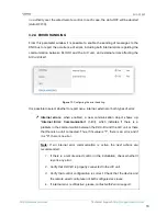
Page 18: ...or both types of error Internal errors when enabled a new communication object shows up Internal Error Communication 1 Bit which indicates if there is a problem in the communication between the KLIC DI and the A C unit or there that there is no unit connected Thus if its value is 1 there is an error and if it is 0 there is no error Note If an internal error communication is active the next actions...

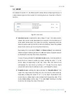
Page 19: ...ontrol error handling functionality must be enabled in order not to cause an abnormal control or behaviour of the air machine 3 2 5 TYPE OF CONTROL The control type of the KLIC DI interface is also parameterised from the General window This can be Master Remote Control or Slave Remote Control depending on whether or not there is an additional wired remote control in the bus Please refer to the Con...

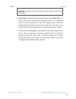
Page 20: ...ng 1bit and Swing 1bit Status By means of this set of objects it is possible to implement the reception of control orders from the bus and afterwards report the updated state of the machine The Swing 1bit 1 bit object permits controlling the slat position as follows Sending the value 0 if the slats are at a still position they switch to the following one according to the following cyclical sequenc...

Page 21: ...ld air flow is outputted directly to particular points of the room where people are supposed to stand Analogously positions 1 and 2 may not be permitted by the A C unit under the Heat mode to prevent hot air accumulation on the top of the room 3 2 7 INTERNAL TEMPERATURE SENDING TIME The Internal Temp Sending Time x1 sec parameter permits defining a period between 30 and 255 seconds to cyclically s...

Page 22: ...he machine had before the power failure ON or OFF Temperature last or custom a new field appears to set the custom initial temperature setpoint between 16ºC and 32ºC Mode Last Auto Heat Dry Fan or Cool Fan Last Minimum or Maximum Swing Last In motion or in any of the 5 Fixed positions available Moreover the status objects can be sent to the bus when applying the initial settings Send initial confi...

Page 23: ...other communication objects specifically enabled in the actuator for this operation Up to 5 different logic functions independent of each other can be enabled each capable of performing between 1 and 4 operations To make use of them they need to be enabled from the following ETS window which appears after selecting Yes under Logical Functions in the General parameter window Figure 15 Configuring t...

Page 24: ...vailable by default and permit switching between the different modes of operation as well as checking the currently active mode respectively In case of having activated the Individual modes option it will be possible to switch from one mode to another by simply sending the value 1 to the control object corresponding to the new mode After that KLIC DI will acknowledge the new mode by sending a 1 th...

Page 25: ... to be received from the KNX bus as percentage values which will be then interpolated according to the specification explained below The same interpolation will be applied over the values sent by KLIC DI through the status object Two levels the fan speed percentages will be interpolated according to Table 3 Initial Speed Percentage Interpolated Speed Percentage Level 0 50 50 Minimum 51 100 100 Max...

Page 26: ...m fan speed level the value 1 sent via the Fan 1 bit object will make the fan speed level change to medium The step control is non cyclical This means that being at the minimum level 33 or 50 any decrease order will be ignored by the unit which will maintain the same fan level unless an order to increase it is received Analogously when the fan speed is at its maximum 100 it will remain unchanged u...

Page 27: ...DPT_Scaling 0 50 Low 51 100 High Fan 1byte 0 50 Low 51 100 High 1 Byte I C W U DPT_Scaling 0 33 Min 34 67 Med 68 100 Max Fan 1byte 0 33 Min 34 67 Mid 68 Max 4 1 Bit I C W U DPT_Switch 0 1 Swing 1bit 0 Fixed pos 1 Motion 5 1 Byte I C W U DPT_Scaling 0 Posit 1 1 20 Posit 2 21 40 Posit 3 41 60 Posit 4 61 80 Posit 5 81 100 In mot Swing 1byte 0 80 Fixed Pos 100 Mot 6 1 Bit O C T R DPT_Switch 0 1 On Off...

Page 28: ... 0 Cool 1 Heat 24 1 Bit I C W U DPT_Step 0 Decrease 1 Increase Fan 1 bit 0 Down 1 Up 25 1 Byte I C W U DPT_SceneControl 0 63 Scenes Receive Selected Scene Value 26 1 Bit I O C T R W U DPT_Switch 0 1 Setpoint Restriction 0 Disable 1 Enable 27 1 Bit I C W U DPT_Switch 0 1 Auto Off 0 Disable 1 Enable 28 1 Bit O C T R DPT_Bool 0 1 Internal Error Communication Unable to Set AC Communication 29 1 Bit O ...

Page 29: ... 50 233 69 9 9 34 C2 59 EH 84 F4 109 JJ 134 P6 159 UF 184 38 209 51 234 6A 10 0A 35 C3 60 EC 85 F5 110 JE 135 P7 160 M0 185 39 210 52 235 6H 11 0H 36 C4 61 EJ 86 F6 111 JF 136 P8 161 M1 186 3A 211 53 236 6C 12 0C 37 C5 62 EE 87 F7 112 L0 137 P9 162 M2 187 3H 212 54 237 6J 13 0J 38 C6 63 EF 88 F8 113 L1 138 PA 163 M3 188 3C 213 55 238 6E 14 0E 39 C7 64 H0 89 F9 114 L2 139 PH 164 M4 189 3J 214 56 23...

Page 30: ...in and send us your inquiries about Zennio devices http support zennio com Zennio Avance y Tecnología S L C Río Jarama 132 Nave P 8 11 45007 Toledo Spain Tel 34 925 232 002 www zennio com info zennio com ...

Reviews: