© Zennio Avance y Tecnología S.L.
Edition 1
Further information
Page 1/2
MAXinBOX 24 v2
Multifunction actuator with 24 outputs (16 A)
ZIOMB24V2
TECHNICAL DOCUMENTATION
FEATURES
•
6 different configurable blocks: shutter channels (up to 12),
individual outputs (up to 24) and 2-pipe fan coil control (up to 6)
•
Outputs suitable for capacitive loads, maximum 140 µF
•
Manual output operation with push button and LED status
indicator
•
2 Master Light controls
•
30 logic functions
•
Output timing
•
Total data saving on KNX bus failure
•
Integrated KNX BCU (TP1-256)
•
Dimensions 68 x 90 x 212 mm (12 DIN units)
•
DIN rail mounting according to IEC 60715 TH35, with fixing
clamp
•
Possibility of connecting different phases in adjacent outputs
•
Conformity with the CE, UKCA, RCM directives (marks on the right side)
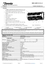
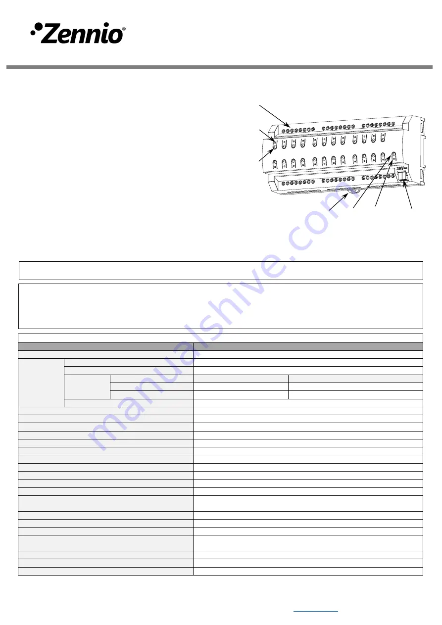
1. Outputs
2. Output status LED
3. Output control button
4. Fixing clamp
5. Programming/Test button
6. Programming/Test LED
7. KNX connector
3
2
7
5
4
6
1
Figure 1: MAXinBOX 24 v2
Programming/Test button: short press to set programming mode. If this button is held while plugging the device into the KNX bus, it enters the safe
mode. If this button is held for more than 3 seconds, the device enters the test mode.
Programming/Test LED: programming mode indicator (red). When the device enters the safe mode, it blinks (red) every half second. The manual mode
is indicated by the green color. During the start-up (reset or after KNX bus failure) and if the device is not in safe mode, it starts a blue blinking sequence.
GENERAL SPECIFICATIONS
CONCEPT
DESCRIPTION
Type of device
Electric operation control device
KNX supply
Voltage (typical)
29 VDC SELV
Voltage range
21-31 VDC
Maximum
consumption
Voltage
mA
mW
29 VDC (typical)
4.3
124.7
24 VDC¹
10
240
Connection type
Typical TP1 bus connector for 0.8 mm Ø rigid cable
External power supply
Not required
Operation temperature
0 .. +55 °C
Storage temperature
-20 .. +55 °C
Operation humidity
5 .. 95%
Storage humidity
5 .. 95%
Complementary characteristics
Class B
Protection class / Overvoltage category
II / III (4000 V)
Operation type
Continuous operation
Device action type
Type 1
Electrical stress period
Long
Degree of protection / Pollution degree
IP20 / 2 (clean environment)
Installation
Independent device to be mounted inside electrical panels with DIN rail (IEC
60715)
Minimum clearances
Not required
Response on KNX bus failure
Data saving according to parameterization
Response on KNX bus restart
Data recovery according to parameterization
Operation indicator
The programming LED indicates programming mode (red) and test mode
(green). Each output LED indicates its status.
Weight
757 g
PCB CTI index
175 V
Housing material / Ball pressure test temperature
PC FR V0 halogen free / 75 °C (housing) - 125 °C (connectors)
¹ Maximum consumption in the worst-case scenario (KNX Fan-In model).


