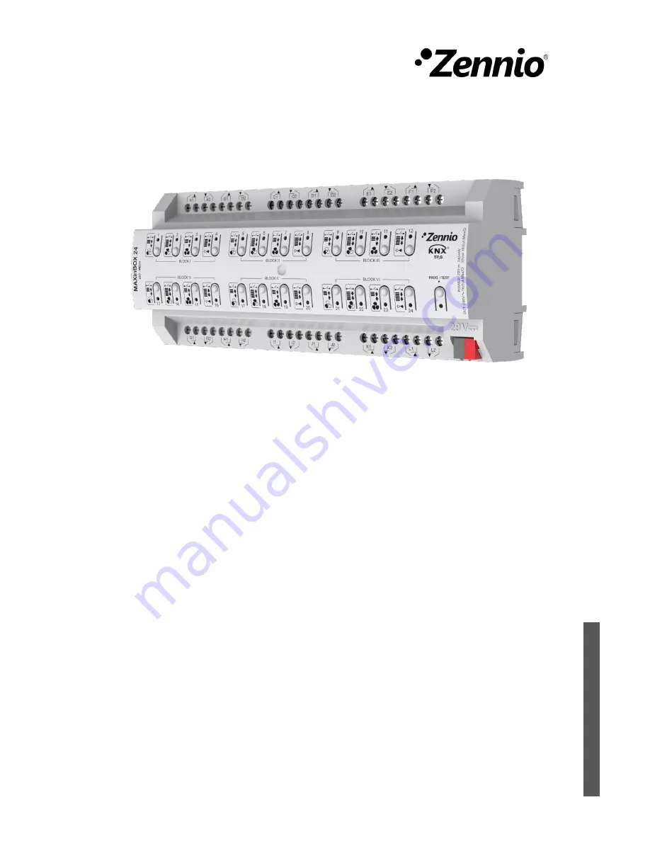
background image


MAXinBOX 24


Multifunction Actuator with 24 Outputs 


ZIO-MB24 


U

S

E

R

 M

A

N

U

A

L


Application programme version: [1.1]  

User manual edition: [1.1]_a 


www.zennio.com


Summary of Contents for MAXinBOX 24 ZIO-MB24

Page 1: ...MAXinBOX 24 Multifunction Actuator with 24 Outputs ZIO MB24 USER MANUAL Application programme version 1 1 User manual edition 1 1 _a www zennio com...

Page 2: ...CONTENTS Contents 2 Document Updates 3 1 Introduction 4 1 1 MAXinBOX 24 4 1 2 Installation 5 1 3 Start Up and Power Loss 6 2 Configuration 7 2 1 General 7 2 2 Outputs 9 2 3 Manual Control 10 2 4 Logi...

Page 3: ...MAXinBOX 24 http www zennio com Technical Support http support zennio com 3 DOCUMENT UPDATES Version Changes Page s 1 1_a Changes in the application program Parameters reorganization...

Page 4: ...thout slats Up to 24 individual ON OFF outputs Up to 6 two pipe fan coil modules where both the fan speed control and the valve control are performed through relays A combination of the above 30 custo...

Page 5: ...the associated LED 6 light in red Note if this button is held while plugging the device into the KNX bus the device will enter into safe mode In such case the LED will blink in red every 0 5 seconds O...

Page 6: ...t whether the output channels should switch to a particular state and whether the device should send certain objects to the bus after the power recovery Please consult the next sections of this docume...

Page 7: ...lity Figure 2 General screen The Manual Control function is enabled by default Once activated Inputs Outputs Logic Functions and Manual Control bring additional tabs to the menu on the left On the oth...

Page 8: ...Object to Send 1 that will be sent periodically with a value of 1 to notify that the device is still working still alive Figure 4 Heartbeat Periodical Alive Notification Note The first sending after...

Page 9: ...uped into two output channels which themselves are grouped into two channel or four output blocks Therefore it is possible to configure up to 6 fan coil modules or up to 12 shutter channels or up to 2...

Page 10: ...est On mode unless disabled by parameter needs to be done by long pressing the Prog Test button for at least three seconds until the LED is no longer red and turns yellow From that moment once the but...

Page 11: ...he status objects will be sent to the bus when corresponding Fan Coil module the behaviour will depend on whether a fan labelled or a valve labelled button is pressed Fan a short or long press will sw...

Page 12: ...l recover the values they had prior to entering Test On As the device is never aware of the actual position of the shutter as the shutter drive does not provide any feedback these values may not show...

Page 13: ...ck enabled disabled unless the above parameter has been Disabled the Lock Manual Control parameter provides an optional procedure for locking the manual control in runtime When this checkbox is enable...

Page 14: ...cution of each function can depend on a configurable condition which will be evaluated every time the function is triggered through specific parameterisable communication objects The result after exec...

Page 15: ...ending for that output channel module such temporisation will be interrupted and only the delay and the action of the new scene will be executed ETS PARAMETERISATION Prior to setting the scene tempori...

Page 16: ...ure 7 Configuration of Scene Temporization Therefore parameter Scene m Z Delay 0 3600 s 0 1440 min 0 24 h defines the delay that will be applied to the action defined in Z for the execution of scene m...

Page 17: ...C T DPT_Trigger 0 1 Heartbeat Object to Send 1 Sending of 1 Periodically 5 16 27 38 49 60 71 82 93 104 115 126 137 148 159 170 181 192 203 214 225 236 247 258 1 Byte I C W DPT_SceneControl 0 63 128 19...

Page 18: ...4 25 36 47 58 69 80 91 102 113 124 135 146 157 168 179 190 201 212 223 234 245 256 267 4 Bytes I O C T R W DPT_LongDeltaTimeSec 0 2147483647 Ox Operating Time s Time in Seconds 15 26 37 48 59 70 81 92...

Page 19: ...t Direction Status 0 Upward 1 Downward 281 309 337 365 393 421 449 477 505 533 561 589 1 Bit I C W DPT_Switch 0 1 Cx Auto On Off 0 On 1 Off 1 Bit I C W DPT_Switch 0 1 Cx Auto On Off 0 Off 1 On 282 310...

Page 20: ...rsed 0 Lower 1 Raise 294 322 350 378 406 434 462 490 518 546 574 602 1 Bit I C W DPT_Ack 0 1 Cx Direct Positioning 1 0 No Action 1 Go to Position 295 323 351 379 407 435 463 491 519 547 575 603 1 Bit...

Page 21: ...DPT_Value_1_Ucount 0 255 FCx Manual Fan Enumeration Control 0 S0 1 S1 2 S2 1 Byte I C W U DPT_Value_1_Ucount 0 255 FCx Manual Fan Enumeration Control 0 S0 1 S1 623 655 687 719 751 783 1 Byte O C T R...

Page 22: ...Bit O C T R DPT_Switch 0 1 FCx Valve Anti Seize Protection Status 0 Not Active 1 Active 635 667 699 731 763 795 1 Bit O C T R DPT_Bool 0 1 FCx Control Value Error 0 No Error 1 Error 636 668 700 732 7...

Page 23: ...l 0 1 LF Function x Result 1 Bit Boolean 1 Byte O C T R DPT_Value_1_Ucount 0 255 LF Function x Result 1 Byte Unsigned 2 Bytes O C T R DPT_Value_2_Ucount 0 65535 LF Function x Result 2 Byte Unsigned 4...

Page 24: ...n and send us your inquiries about Zennio devices http support zennio com Zennio Avance y Tecnolog a S L C R o Jarama 132 Nave P 8 11 45007 Toledo Spain Tel 34 925 232 002 www zennio com info zennio c...

Reviews: