Technical Documentation
© Zennio Avance y Tecnología S.L. Edition 3 Further information
www.zennio.com
Page
2
/
2
WIRING AND ASSEMBLY DIAGRAMS
SAFETY INSTRUCTIONS
Do not connect Mains Voltage (230 V) or any other external voltages to any point of the bus.
Connecting an external voltage might put the entire KNX system at
risk.
Make sure during the installation that there is always sufficient insulation between the mains voltage 230V and the bus or
the extension inputs.
Once the device is installed, the output terminal should not be accessible.
OUTPUTS SPECIFICATIONS AND CONNECTIONS
Contact type
Potential free outputs through bistable relays with tungsten pre-contact.
Disconnection type
Micro-disconnection
Rated current by output
16(6)A * 250V AC (4000 VA)
16(6)A * 30V DC (480W)
Maximum inrush current
800A/200
μs (fluorescent lamps)
165A/20ms (resistive lamps)
Outputs per common
1 individual output
Different phases connection
Possibility to connect different phases in adjoining outputs
Maximum current
80A
Maximum power
Resistive load
4000W
Inductive load
1500W
Connection type
Terminal block (screw)
Recommended cable section
0,25 mm² to 4 mm²
Cable type
Stranded or solid wire.
Maximum response time
50 ms
Expected life
Mechanical (min)
3 million operations (60cpm)
Electrical (min.)
100.000 cycles at max. current (6cpm and resistive load)
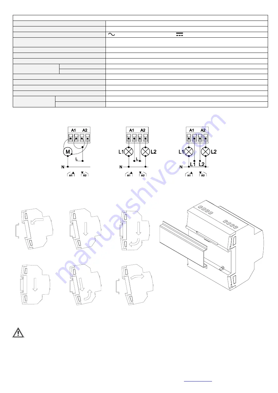
Attaching MAXinBOX 8 to DIN rail:
Removing MAXinBOX 8 from DIN rail:
Figure 3. Installation of MAXinBOX 8 on DIN rail
Figure 2. Wiring examples (from left to right):
channel A as shutter channel and individual outputs with the same and
different phases.


