
© Zennio Avance y Tecnología S.L.
Edition 4
Futher information
Page 2/2
SAFETY INSTRUCTIONS
•
Installation should only be performed by qualified professionals according to the laws and regulations applicable in each country.
•
Do not connect the mains voltage nor any other external voltage to any point of the KNX bus; it would represent a risk for th e entire
KNX system. The facility must have enough insulation between the mains (or auxiliary) voltage and the KNX bus or the wires of other
accessories, in case of being installed.
•
Once the device is installed (in the panel or box), it must not be accessible from outside.
•
Keep the device away from water and do not cover it with clothes, paper or any other material while in use.
•
The WEEE logo means that this device contains electronic parts and it must be properly disposed of by following the instructi ons at
http://zennio.com/weee-regulation.
OUTPUTS SPECIFICATIONS AND CONNECTIONS
CONCEPT
DESCRIPTION
Number of outputs
4
Output type
Potential-free outputs through bistable relays
with tungsten pre-contact / Micro-disconnection
Rated current per output
AC 16(6)A @ 250VAC (4000VA)
DC 7A @ 30VDC (210W)
Maximum load
per output
Resistive
4000W
Inductive
1500VA
Maximum inrush current
800A/200μs
165A/20ms
Different phases connection
Possibility of connecting different phases in
adjoining outputs
Maximum current per block
40A
Connection method
Screw terminal block
Cable cross-section
1.5-4mm² (IEC) / 26-10AWG (UL)
Outputs per common
1
Maximum response time
10ms
Mechanical lifetime (min. cycles)
3 000 000
0-10V OUPUT SPECIFICATIONS AND CONNECTIONS
CONCEPT
DESCRIPTION
Número de salidas
2
Ouput type
0-10VDC
Maximum load per output
1.5mA
Connection method
Screw terminal block
Cable cross-section
0.5-2.5mm² (IEC) / 26-12AWG (UL)
Output per common
1
INPUTS SPECIFICATIONS AND CONNECTIONS
CONCEPT
DESCRIPTION
Number of inputs
4
Inputs per common
4
Operation voltage
+3.3VDC in the common
Operation current
1mA @ 3.3VDC (per input)
Switching type
Dry voltage contacts between input and
common
Connection method
Screw terminal block
Cable cross-section
0.5-2.5mm² (IEC) / 26-12AWG (UL)
Maximum cable length
30m
NTC probe length
1.5m (up to 30m)
NTC accuracy (@ 25°C)
±0.5°C
Temperature resolution
0.1°C
Maximum response time
10ms
⚠
In order to ensure the expected status of the relays,
please check that the device is connected to the KNX bus
before energizing the power circuit.
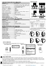
WIRING DIAGRAMS
Figure 2: wiring example for 4-pipe fan coil with 4-
speed fan (up) and for 2-pipe fan coil with 3-speed
fan (down).
Attaching MAXinBOX FC 0-10V VALVE to DIN rail:
Removing MAXinBOX FC 0-10V VALVE from DIN rail:
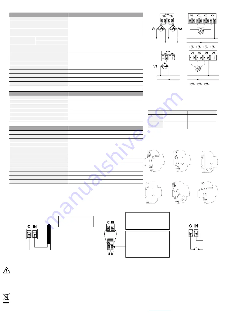
* The micro switch number 2 in the ZN1IO-DETEC-P must be in
Type B position
to work properly.
INPUTS CONNECTION
Any combination of the next
accessories
is allowed on the inputs:
Zennio temperature
probe.
Up to two motion sensors
can be plugged into the
same device input (parallel
wiring)
Motion
sensor
screw
terminal.
Motion sensor references:
ZN1IO-DETEC-X
ZN1IO-DETEC-P
*
Temperature Probe
Motion Sensor
Switch/Sensor/
Push button
G/L
G0/N
G/L
G0/N
G/L
G0/N
G/L
G0/N
0-10V outputs
according to the number of fan
coil pipes
:
Fan Coil
0-10V output
Valve function
4 pipes
V1
Cooling valve
V2
Heating valve
2 pipes
V1
Cooling and/or
heating valve


