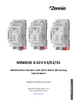
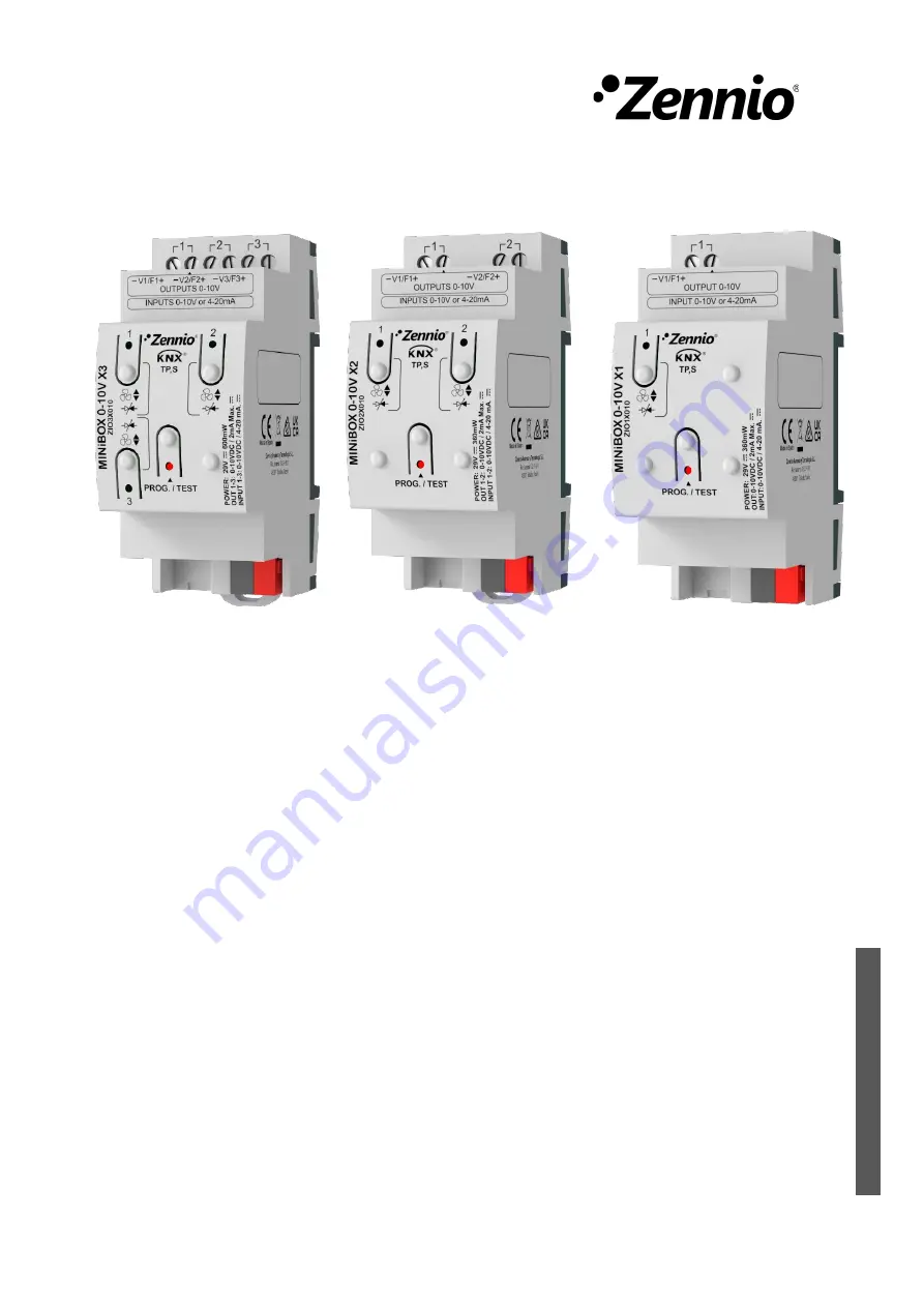
Zennio MINiBOX 0-10V X3, User Manual
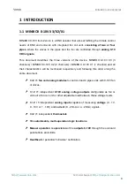
The Zennio MINiBOX 0-10V X3 is a high-quality, reliable device perfect for controlling lighting systems. Easily set up and configure with the included User Manual, available for free download from 88.208.23.73:8080. Get the most out of your MINiBOX with this comprehensive manual.
Share
Download
Reviews:
No comments
Related manuals for MINiBOX 0-10V X3

20
Brand: J4C Pages: 4

20
Brand: Vacon Pages: 62

ControlMaster CM15
Brand: ABB Pages: 28

650 series
Brand: ABB Pages: 128

ACS880 Series
Brand: ABB Pages: 50

ABILITY SSC600
Brand: ABB Pages: 42

AC 800M
Brand: ABB Pages: 120

ACH400 Series
Brand: ABB Pages: 28

TZIDC-110
Brand: ABB Pages: 59

ACS355 series
Brand: ABB Pages: 139

LME620-AI
Brand: ABB Pages: 15

PST30
Brand: ABB Pages: 10

LME620-AI
Brand: ABB Pages: 30

LME620-AI
Brand: ABB Pages: 44

XFC G5
Brand: ABB Pages: 2

ControlMaster CM15
Brand: ABB Pages: 4

Leroy-Somer R180
Brand: Nidec Pages: 20

5800 Series
Brand: S&C Pages: 34


